 David H. Bronke
I've now put together the driver for the heating element in the soldering iron, and started testing. Here's a close-up of the second stage of the driver (soldered to cheap perfboard because this MOSFET is in an SO-8 package):
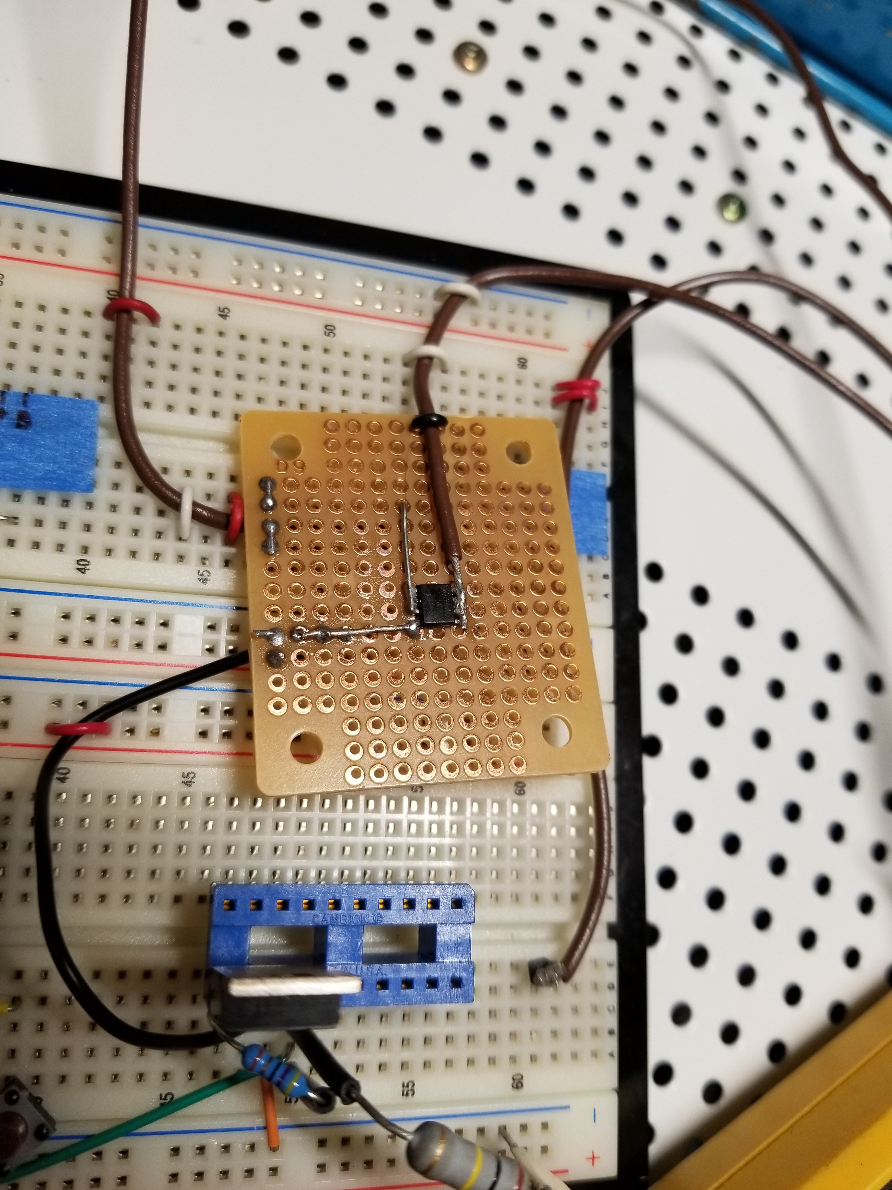
Note that the first version of this was just leads soldered to one of the chips, but on that one, the gate pin ended up breaking off, despite some attempted strain relief. I should really have known better.
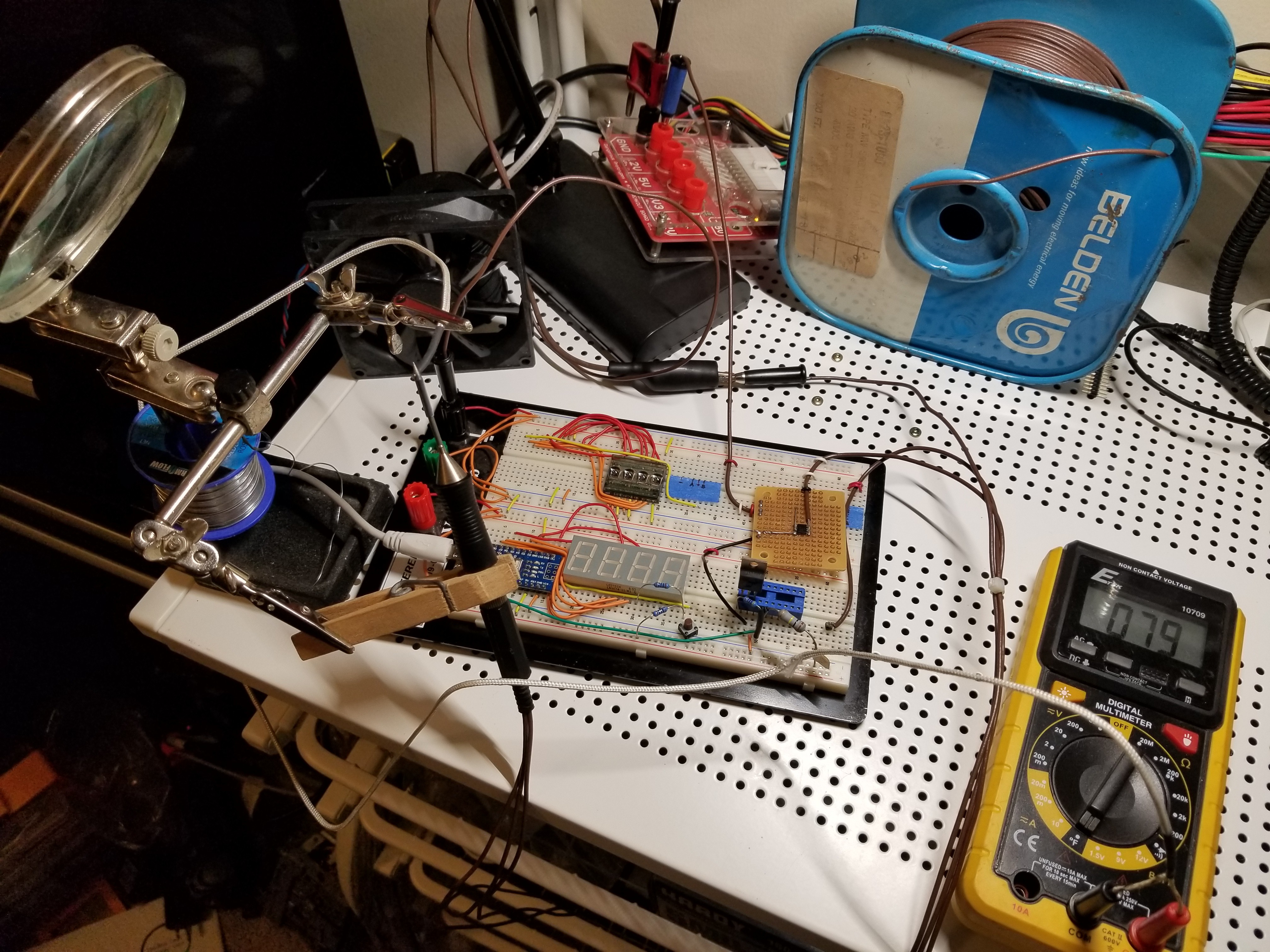
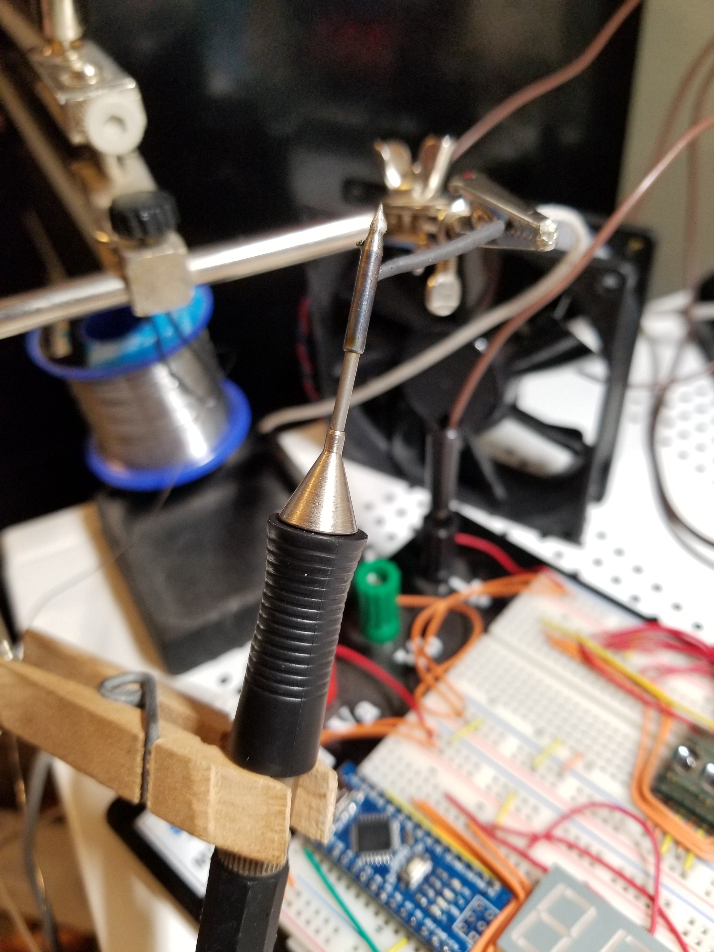
Next, I plugged everything in, and set up the soldering iron tip with a thermocouple touching it so I can check the temperature as it heats:
Look at how nice and clean that tip is! Well... it didn't stay that way for long. I made the mistake of actually following the schematic and connecting the iron supply to 12V... and I wasn't able to disconnect it quickly enough when it started heating like crazy, so it ended up getting up to around 500 degrees Fahrenheit. This oxidized the tip, though I was able to fix that with some flux and re-tinning... but the rest of the tip piece is now nicely blued:
Good news, though: I didn't burn out the tip or any of the components! (though some smoke did emanate from the headphone jack, and it looks like the insulator in it has melted some... I might have to see about replacing that with a jack that makes a better connection)
I've been able to test out heating using different duty cycles (so far I'm using a 200ms period, though I may increase that) and it seems that the iron actually heats pretty quickly even on 5V instead of 12V. (though I'll need to check whether or not I can actually pull 2.63A from the Arduino's supply pins... I get the feeling that might not be feasible, which will mean I'll need to use something other than USB for the 5V supply) It even works OK on 3.3V, but doesn't actually heat very quickly. (though, to be fair, I've only tried that with up to a 15% duty cycle, so it may still give somewhat passable results if I try a higher duty cycle... and at 3.3V the heater will only draw 1.74A)
Next step will be to get the temperature sensor hooked up so I can start building a model based on my thermocouple readings... and then, on to PID control!
Also, since the heater switching causes my power supply to click audibly, I should probably figure out how to filter the transients out of the supply rails before trying to run this thing entirely off USB.
Discussions
Become a Hackaday.io Member
Create an account to leave a comment. Already have an account? Log In.