 shlonkin
ATtiny10 resources
UPDATE:
A huge thanks to Keri DuPrey, Nat Blundell and others who have been continually improving the code. The latest version is here:
ATtiny4_5_9_10_20_40Programmer.ino
And a useful GUI by Keri is here:
GUI: ATTiny4_5_9_10_20_40_Programmer.jar
Also, avr-libc 1.7 and newer support ATtiny10! I have not tried it, but I reckon you can now use avr-gcc for the tiny10. However, with only 1kB of program memory, assembly is still useful.
The ATtiny10 is an intriguing little thing. It's the size of a grain of rice and has just 6 little SOT23 pins, but inside lies all the capabilities of an 8-bit AVR microcontroller. Everything from 4 analog input channels to a 16-bit timer with 2 possible pwm outputs to all your basic digital functionality. And at 45 yen a piece, there's little reason not to pick one up to play with. Or two... or ten.
Then once you get home and sit down at your computer, you realize that you are in for a bit more homework than you expected. ICSP doesn't work, common C compilers don't work, hardly anyone online has done DIY stuff with them.
But hark! Do not forsake hope. I am here to aid you on your journey. First, I will guide you to the references that aided me: (The most useful of these was the last one, but it is in Japanese.)
Hardware
Now let's think about hardware. If you are willing to purchase an AVR programmer, go ahead. It's an easy solution that will definitely work. In that case, you can skip down to the assembly examples.
If you would rather do this the hard way(possibly more educational and satisfying), I'll show you how to program the ATtiny10 with only your Arduino, AVR Studio(or anything that will turn your assembly into a hex file) and a few resistors. Also, if you want to make use of all four I/O pins, you will need a 12V power supply for reprogramming.
Here is the basic hardware setup. Thanks to pcm1723 for this drawing and so much more.
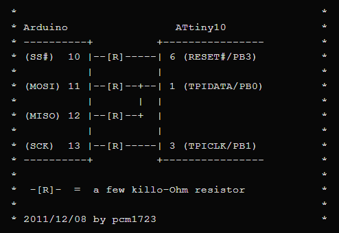
Really, some of those resistors may be unnecessary, but they don't hurt. You can see that it is making use of the usual SPI pins, and indeed we are going to make use of the SPI library to handle the communication details. Anyway, I got tired of setting up wires on a breadboard, so I just made this little pcb with 2.2kohm resistors that plugs right into the Arduino. It also has a connector and jumper for applying 12V to the reset pin. This is only necessary if you disable the reset pin for I/O use.

Note that pin 1 goes in the top right corner. It faces the same direction as the chip on the arduino. Also note that the ATtiny10 needs to be on an adapter to plug into the DIP socket. I would like the option of using the chips without an adapter, so I want to make something that clamps the chip onto a breakout board without solder. I'll post again if I make something like that.
Software
Well, that was simple enough. Now for the software.
First, you will need to generate a hex file for your program. One simple and guaranteed to work method is by using AVR Studio, which is free to download from the Atmel website(here). Set your device to ATtiny10, make a new assembly file project thing, write your code, and click "build solution" in the build menu. Your hex file will be buried in a folder in the AVR Studio projects folder. Look for a folder with your project's name and somewhere inside will be a debug folder. hex is inside of that one.
Then we have to get the program onto the chip.
A big thanks again to pcm1723 for getting me started with the code for the arduino. They posted a simple sketch that uses the TPI interface to read all the memory on the chip and send it via serial to a computer. It was then up to me to extend this code to include all the necessary programming functions. You can find the original code on the fourth link up above. Most of it is included in the code below.
*EDIT* - Thanks to Keri DuPrey for making some nice changes to the code. See the comments below to find a link to the updated code. Changes: supports tiny20 and 40, read,program and verify in one streamlined command, can handle programs larger than 1024 bytes.
*UPDATE* - Thanks to a commenter for pointing out that the fuse setting and clearing didn't work. With their help I have updated the code and it should work now.
- ATtiny10Programmer.ino(Better yet, use Keri DuPrey's code at the top of the page.)
Upload this sketch to an arduino. I ran into a very strange problem where it just wouldn't work right if the sketch size was much larger than 7,000 bytes. It would just hang or reset while programming an ATtiny10. I cannot fathom why this is. There should be more than ample memory on the arduino. If anyone has an idea, please let me know(leave comment on home page). Anyway, this version compiled to 6,996 bytes and worked fine.
Then power off(unplug) the arduino, connect the ATtiny10 as shown, and power up the arduino again. Open up the serial monitor in the tools menu. Set the serial speed to match the one used by the arduino. The default is 38400. If everything is working so far, you should see the message
NVM enabled
ATtiny10 connected
If you don't see this, either you aren't using an ATtiny10 or there could be a hardware problem. After you get this far, you can start using the programming functions. To do this, input the one-character commands described below. Only send one command at a time because some of them require additional input.
Commands:
- D = dump memory. Displays all current memory on the chip
- E = erase chip. Erases all program memory
- R = read program. Sends the program to the arduino. After sending this command you have 20 seconds to copy and paste the entire contents of a .hex file into the serial monitor and send. You can do the whole file at once. If it was successful, you should see "program received".
- P = write program. After reading the program with the R command, use this to write the program to the ATtiny10.
- V = verify. Verifies that the program was written correctly. If not, it will display the errors.
- F = finish. Not necessary, but this disables further access until the arduino is reset.
- S = set fuse. Follow the displayed instructions to program one of the three fuses.
- C = clear fuse. Follow the displayed instructions to UNprogram one of the three fuses.
The 'D' command is quite a useful and harmless way to test your programmer and the chip. It simply reads all the memory on the ATtiny10 and displays it in the serial monitor in an easy to read way. You may want to avoid the 'S' and 'C' commands unless you are sure you want to mess with the fuses. There are only three fuses. One sends the clock signal to a pin, one enables the watchdog timer, and one disables the reset pin so you can use it for I/O. If you disable the reset pin, I hope you have a 12V power supply, because you will need it the next time you want to program the chip.
A little caution: if you want to verify after programming, be sure to press shift+v and not ctrl+v as I have done many times. ctrl+v will probably paste your hex file to the monitor again. If you accidentally send it, you will see a lot of strange behavior as the programmer reads 'C', 'D', 'E', 'F' commands along with a bunch of ignored characters. Don't worry, the worst that could happen is that you will erase your chip and disable further programming until you reset the arduino. Just reset and try again.
Examples
OK, now that you can program the chip the hard part begins. Actually making an interesting program. If you are like me and this is the first time you have used assembly for AVRs, just google "AVR assembly tutorial" and you will find everything you need. It takes a little more work than something like C, so I will give you some simple programs that make use of the various functionality of the chip. They are by no means perfect or interesting, but you can use them as building blocks.
- tinyblink.asm - blinking LED uses delay and digital output
- pwm.asm - pulse width modulation uses timer
- interrupts.asm - uses three different types of interrupts
- analog.asm - uses the analog to digital converter
Good luck.