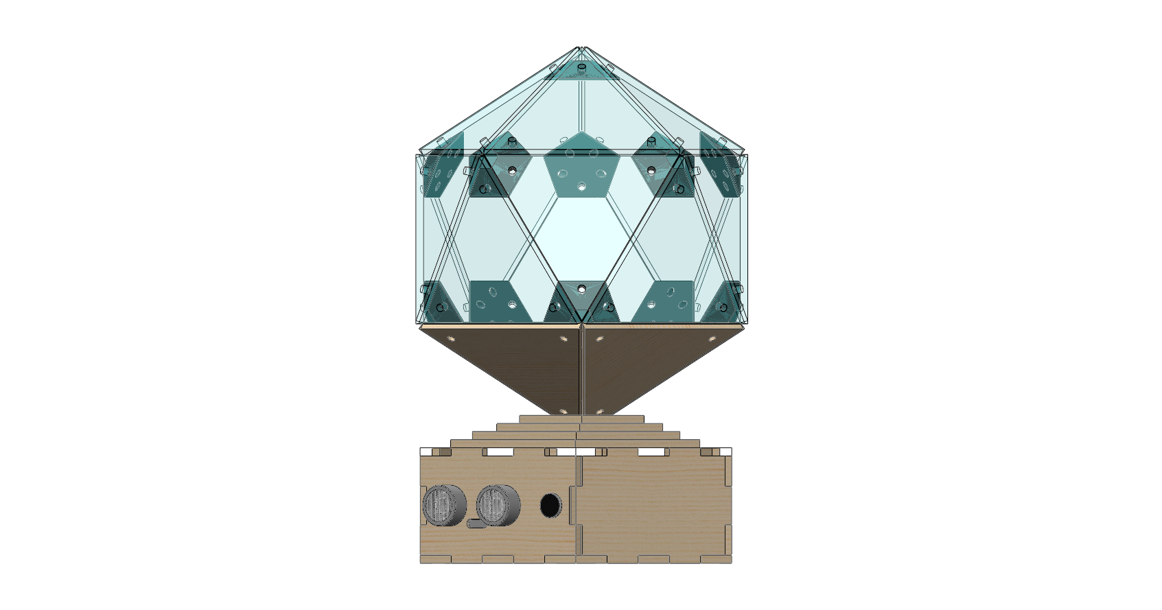
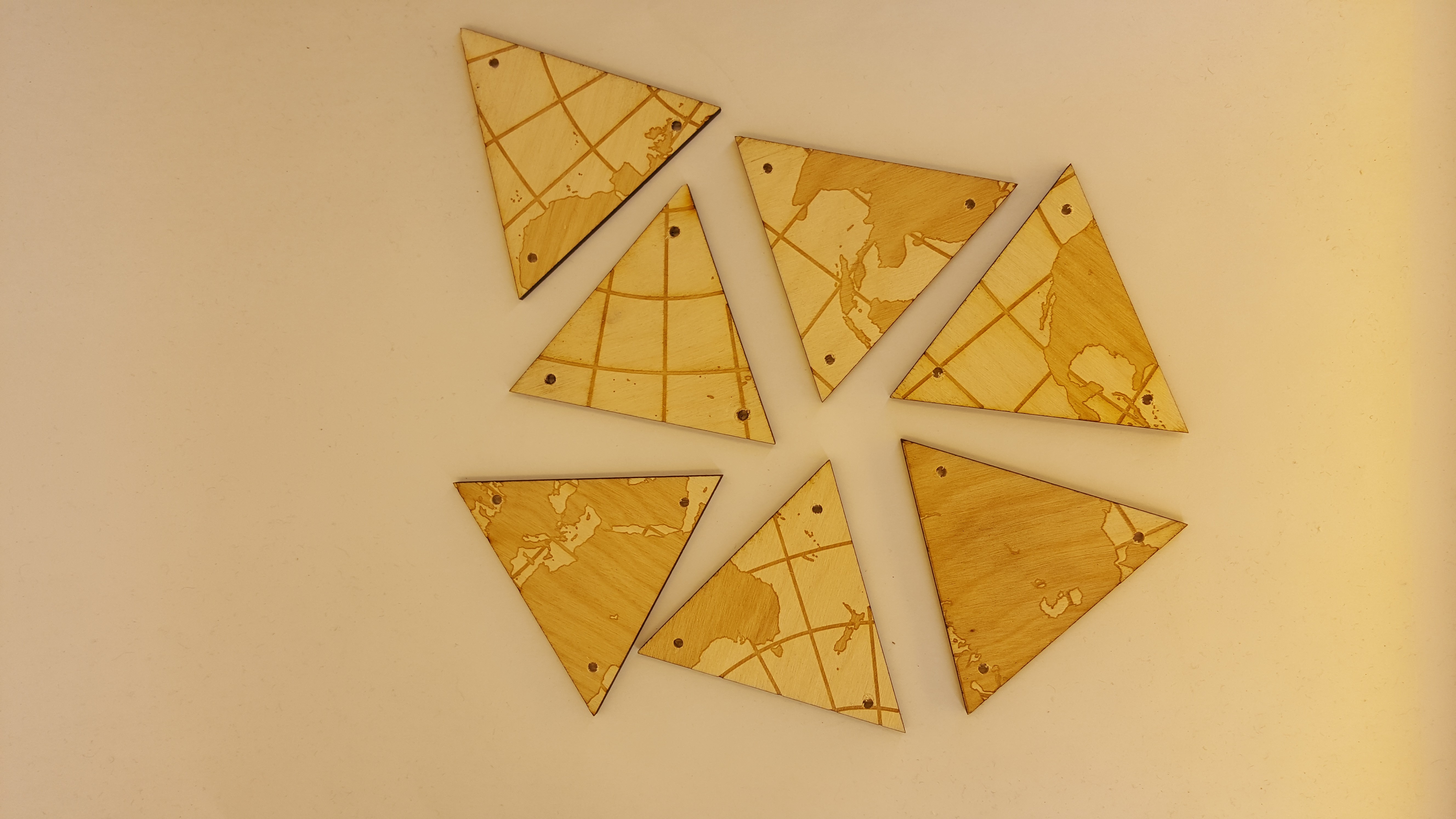
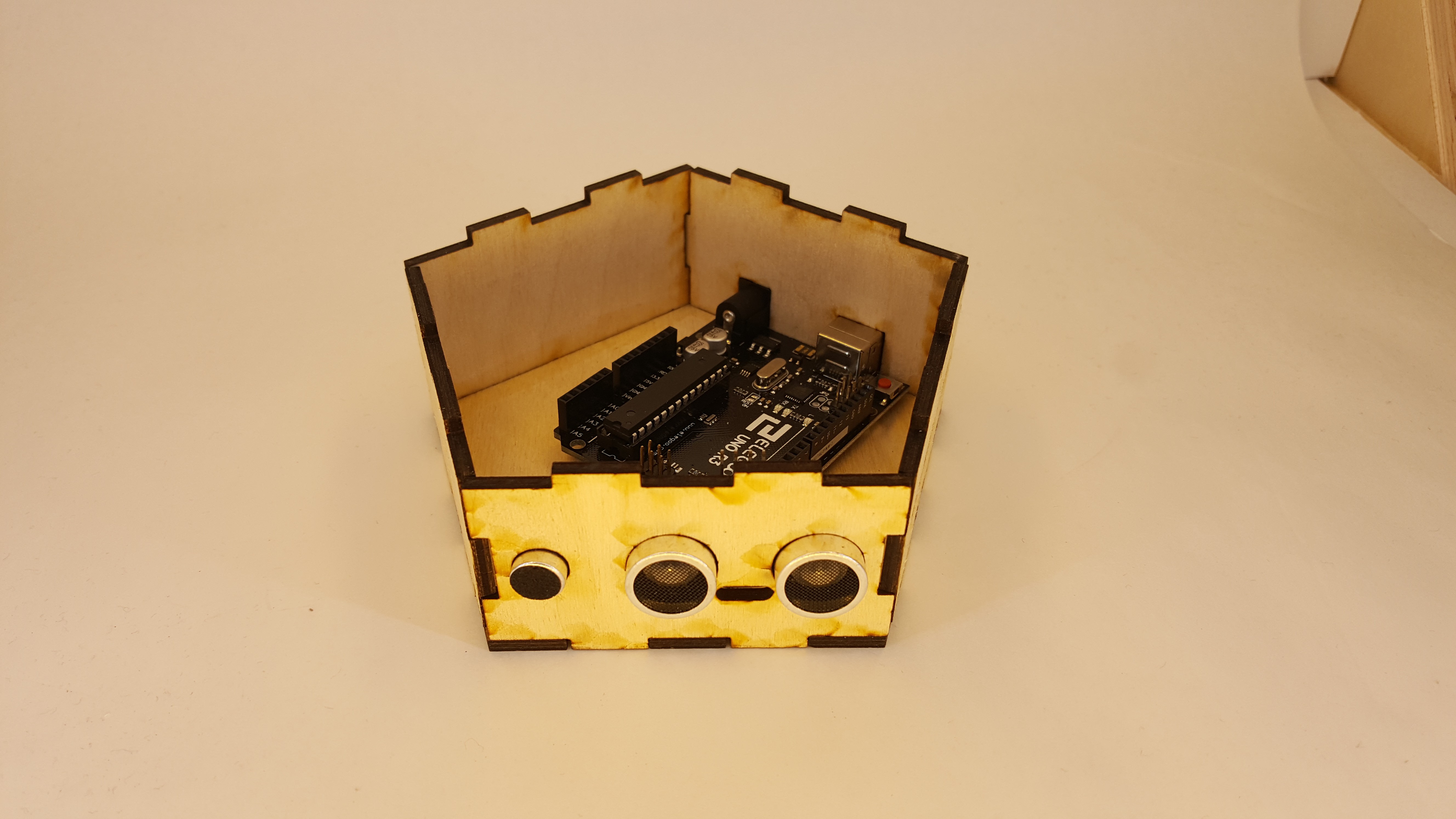
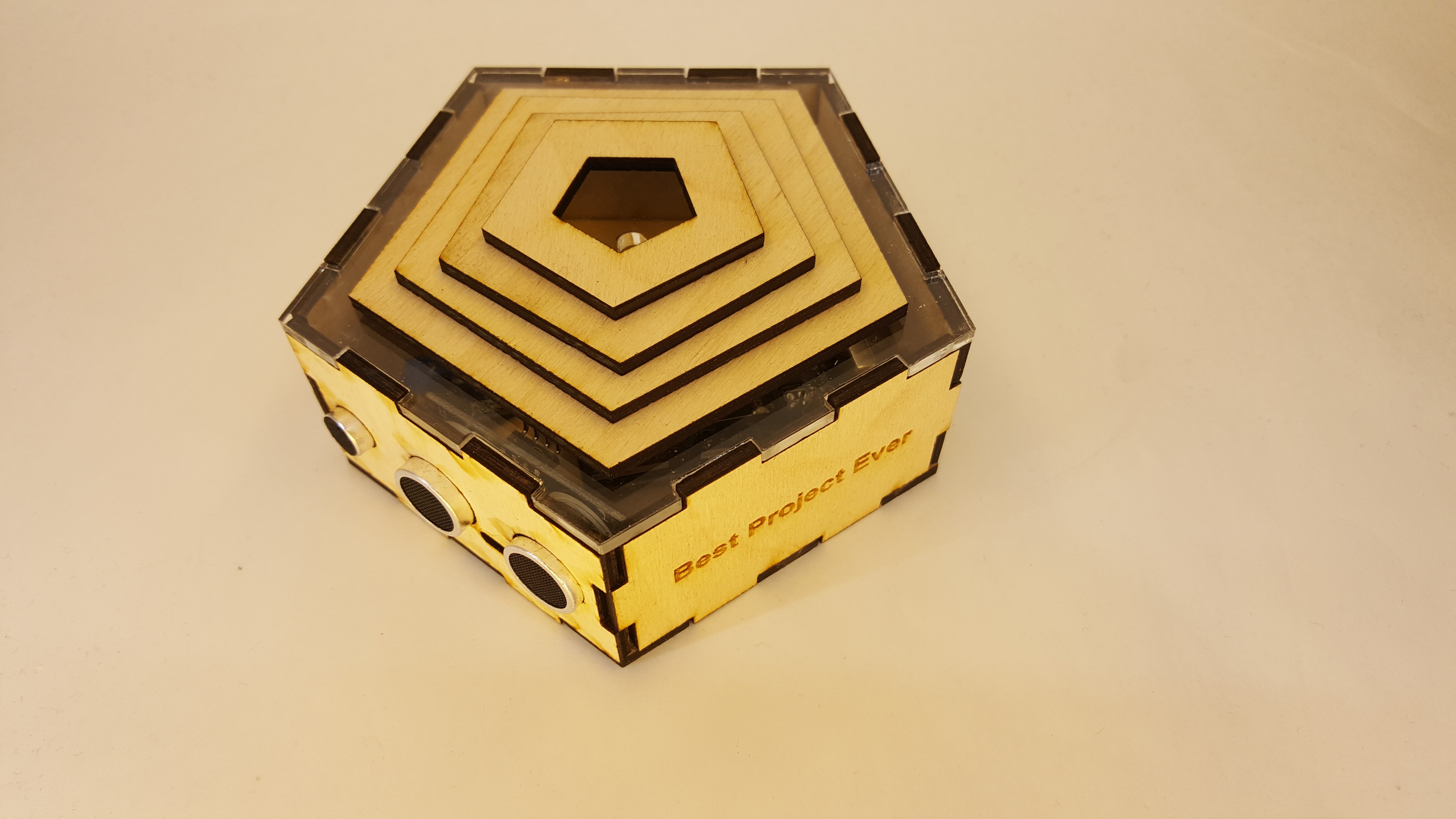
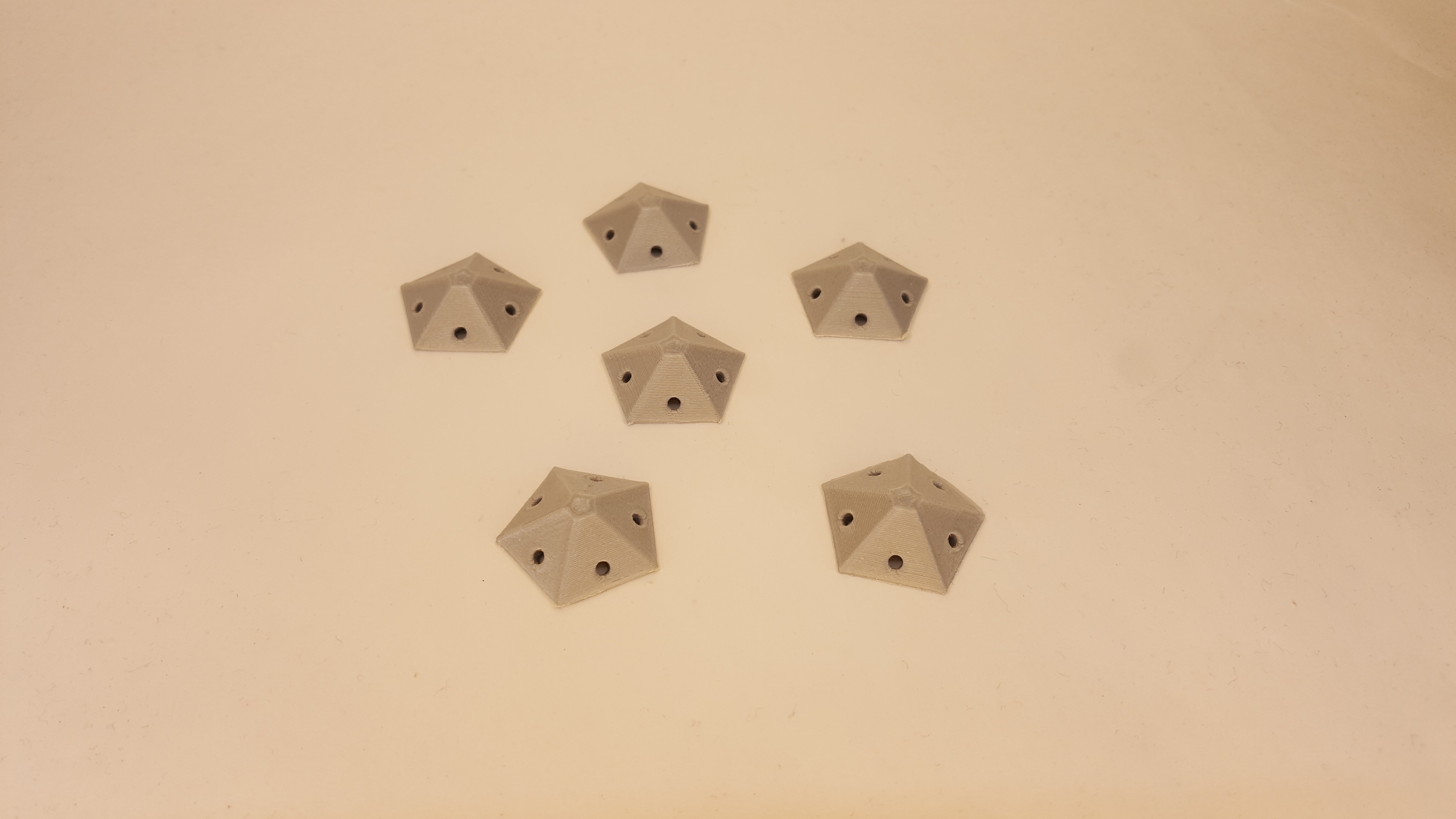
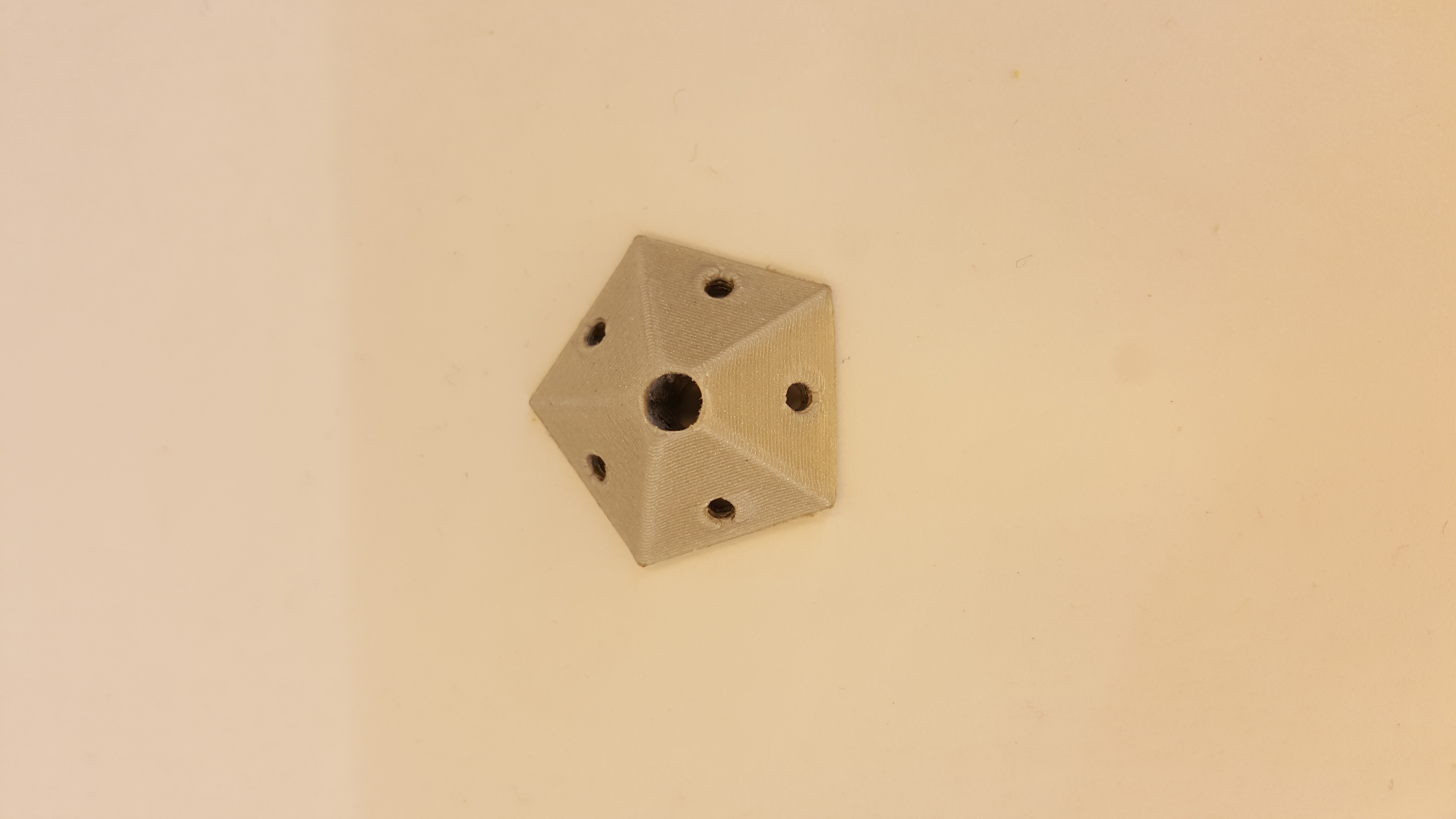
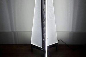
This is a project that I worked on for a class to demonstrate knowledge in 3D printing, laser cutting, and the use of power tools. We used 1/8" birch plywood and 1/8" clear acrylic to laser cut the globe and base, 3D printed icosahedron joints, and fastened the triangle panels together with socket head screws.
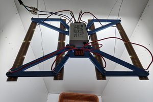
The idea was based off Gavin Smith's Dymaxion Globe, with some help from Kim Stroman's revised map, and lastly Mike's version with the stand. The stand in this version is modified to house electronics and sensors to control LED light strips which are wired through the bottom of the globe. Right now either motion in front of the sensor or a loud clap will trigger the LEDs to turn on like a latching switch.
Each side of the triangle panel measures 3", making the total height of the globe just under 6". The entire assembly comes out to be about 4.75" x 8".
 Stanislas Bertrand
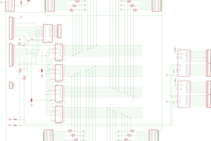
 Niko
Niko
 hackaday