The current software implementation allows to perform 360° scans with a rotation angle of 0.45° between two measurements. At each position the voltage output of the distance sensor is sampled 100 times at a sample rate of 1 kHz. The average value of these samples together with the current angle position is transferred via USB to the PC. The incoming data stream is stored in a csv file for later analysis in Octave. A black paper on the floor and walls made from cardboard form the test environment in which the distance sensor assembly can be put at arbitrary positions.
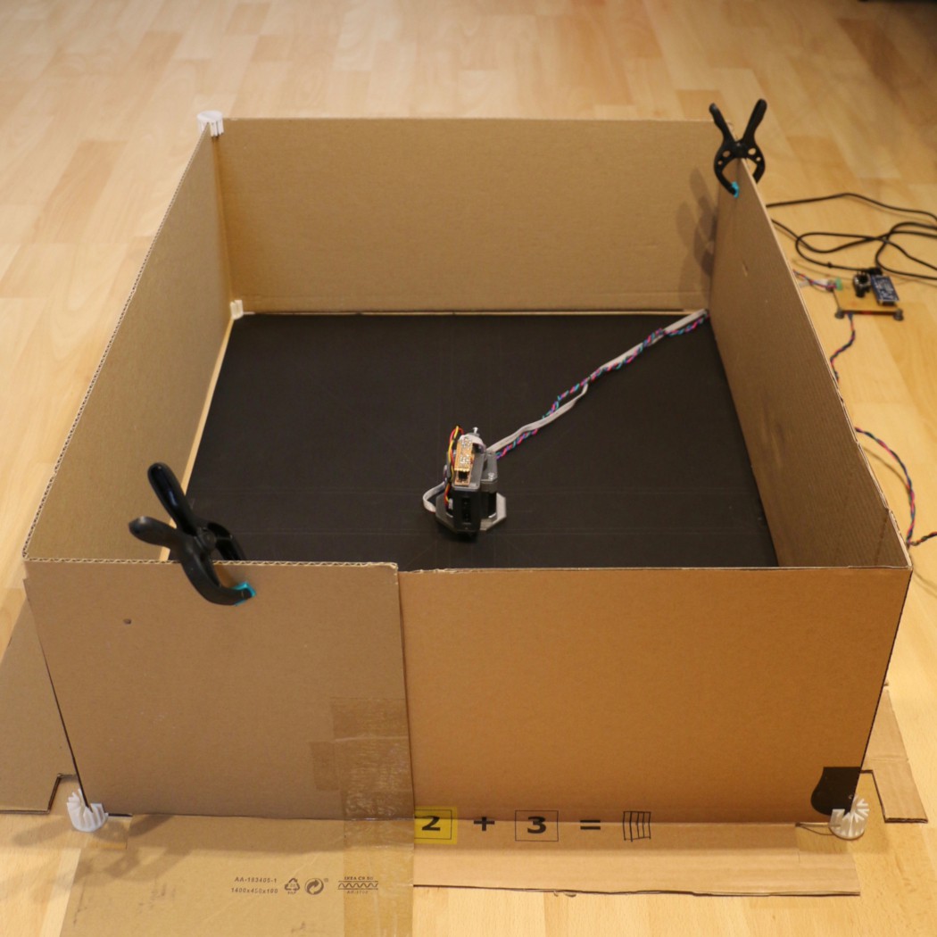
I performed a first scan using this setup with the sensor assembly put into the center position. The generated csv file contains a tuple of current angle and object distance per line [alpha, d] which is the measurement result in polar coordinates. A transformation to cartesian coordinates is necessary to plot the data as a 'map'.
First the angle alpha in degree needs to be converted to radian:
Next the x and y coordinates can be obtained using the following formulas:
The graphs below show the measurement data before and after the coordinate transformation.
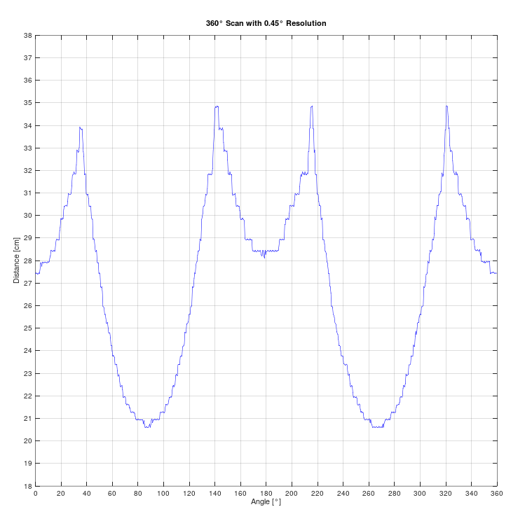 | 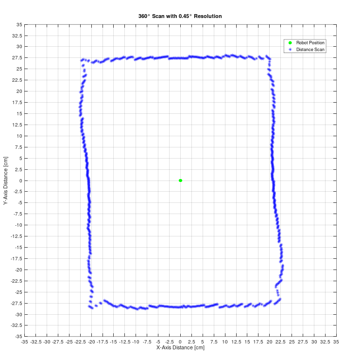 |
This is a very satisfying result for a first try as the generated 'map' reflects the rectangular shape of the test environment.
Putting an obstacle into the test environment leads to the following graph of which two observations can be made.
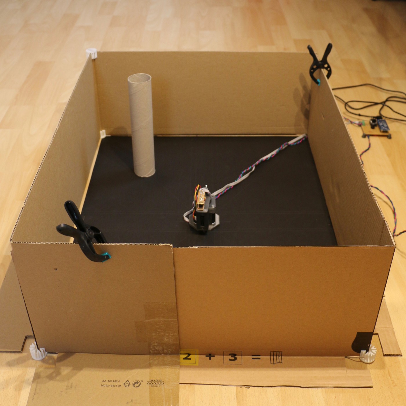 | 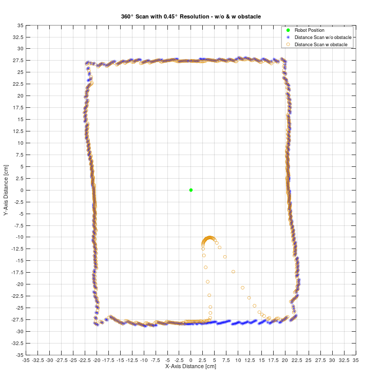 |
First the sensor assembly shows a good reproducibility of the distance scans. The two consecutive measurements almost match completely in the range without obstacle. The second observation is about how the distance scan varies in the transition between the obstacle in the foreground and the wall behind leading to larger gaps between the measurements. I will look into that later to see if this information can be used to improve the mapping or to implement an adaptive scan resolution algorithm.
Next on to making the scan angle resolution configurable and to learn how to use this data in ROS.
Discussions
Become a Hackaday.io Member
Create an account to leave a comment. Already have an account? Log In.