After building the auxiliary section and testing I’ve called this one done. The spice file is posted as ‘r3’ and the schematic is below. The basic design & theory of operation are as described in the Revision 2 post. The changes are in component values of each of the capacitive supplies to ensure proper operation. Standard gate trigger TRIACs require ~ 35mA to reliably trigger and with the bias required by the control circuits the total current demand is a bit over 40mA.
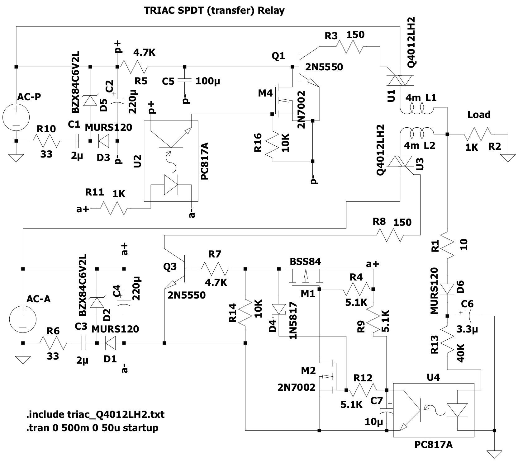
A problem with capacitive supplies is that they are current limited based on the time constant. With a half-wave rectifier they must support the supply voltage for a half-wave. At 60Hz this is approximately 8.333mS. With a 6V supply and assuming the AC supply peaks at 170V, the drop across the capacitor is 164V. The basic formula for capacitance is C = (A * s)/V. Rearranging to solve for time: s = (C * V)/A = (.000001 * 164) / .04 = 4.1mS. That’s only half the required time. Increasing the capacitance to 2uF gets it to 8.2mS; close enough.
C1 & C3 were increased to 2uF and R6 & R10 reduced to 33Ω to reduce dissipation at the expense of higher inrush current. Even with these changes the ripple on the auxiliary (a+) supply was large enough that the latch circuit would not reliably function. The more proper way to solve this would have been to redo the latch with BJTs since they are current controlled and in this application would probably work okay. The easy way out was to increase the bulk capacitance of C4 to 220uF which was just enough. I did the same for C2 on the primary to ensure it had some margin too.
With a few exceptions the remainder of the component ratings & tolerances are forgiving. Components rated for 25VDC are fine and currents are less than 10mA. R13 should be rated for at least 3/4W since it is dropping almost the entire AC voltage. It’s value doesn’t need to be exact (to get to a standard value) but limit the current to 10mA and make sure to check the dissipation. C6 should also be rated for 250VDC. All of the MOSFETs should have logic-level gates. M4 won’t be destroyed by C5’s discharge as long as M4’s Rds(on) limits current to its pulse rating. Q1 & Q3 should have an hfe > 100. They will sink about 35mA but the voltage drop is small so TO92 packages are fine. Make sure a low Vf schottky diode is used for D4 to ensure adequate gate voltage for M2. Also C1 and C3 should be rated for 250VAC. The opto-isolators used don’t have any special requirements; Fairchild FODM121 were used for the prototype.
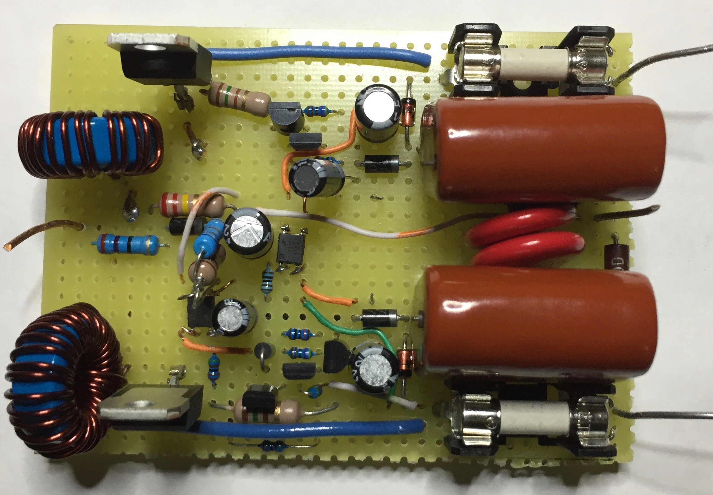
If you build this be sure to fuse both the primary & auxiliary (AC-P, AC-A) inputs. Size according to the load (I used 2A slo-blo). As you can see from the pics on the final build I didn’t do anything special for thermal management which, for my application, wasn’t necessary. However, most TRIACs will have a Vf of ~ 1V and loads drawing more than 500mA will destroy the TRIACs without heat sinking or other thermal management. Last, I also included 250V MOVs across the output side of each fuse to provide additional transient protection (red disks between supply caps).
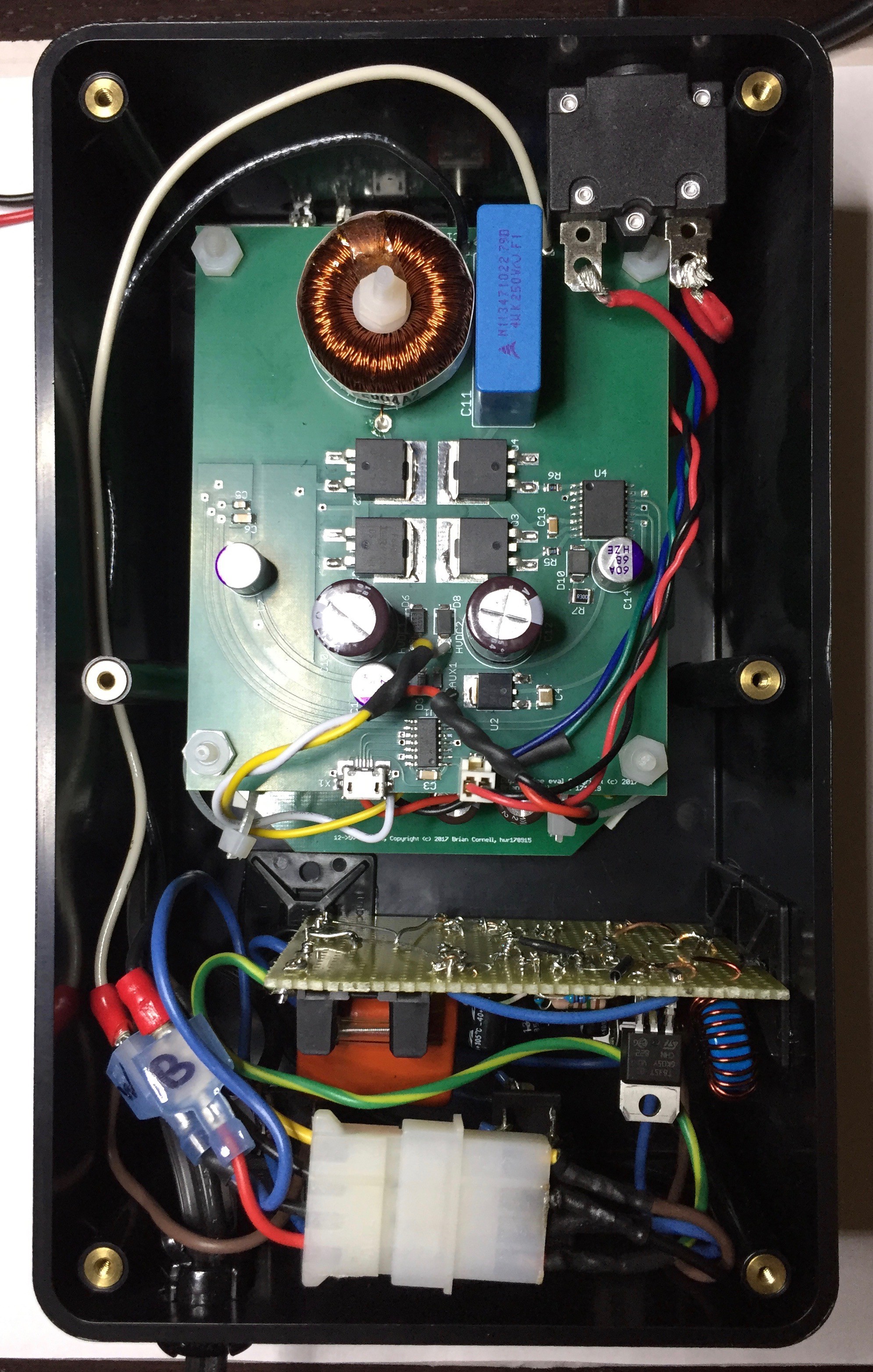
This thing actually works well; I integrated it with my TS50 project to switch between utility & PV AC. Switching time is about 300mS which exceeds the hold-up time of most gadgets so you won’t get uninterrupted operation. You could reduce the value of C7 to shorten but be sure to test.
Back to the capacitive supplies. As shown above this design operates on the edge of what’s possible with 2uF capacitors. Higher currents require larger capacitors, higher apparent power, and diminishing returns. This is important because a TRIAC’s gate bias has a negative temperature coefficient; higher temps=lower gate current, lower temps=higher. This means that at ambients less than 10C (this is a guess, I didn’t test) it may not work reliably but higher temps won’t be a problem.
Discussions
Become a Hackaday.io Member
Create an account to leave a comment. Already have an account? Log In.