 Beaglebreath
Last weekend I downloaded the software needed to design a printed circuit board, and have it appear on a delivery truck at my front door 5-days later. Viola. That was cool. and since this was my first purchase, they threw in all the parts I would need to build this as well. I assembled a circuit board on Friday night and began testing the GPIO outputs which control three transistors, which are doing level shifting from 3.3 volts to 5 volts for the quadrature decoder chip. The three control pins put the quadrature counter chip into one of several modes including; reset to zero, count mode, decode and output high-byte, output low-byte. The decoder chip has a 8-bit parallel data bus for output of the 16-bit counter output. one of the inputs, selects whether the high or low byte appears on the output pins.
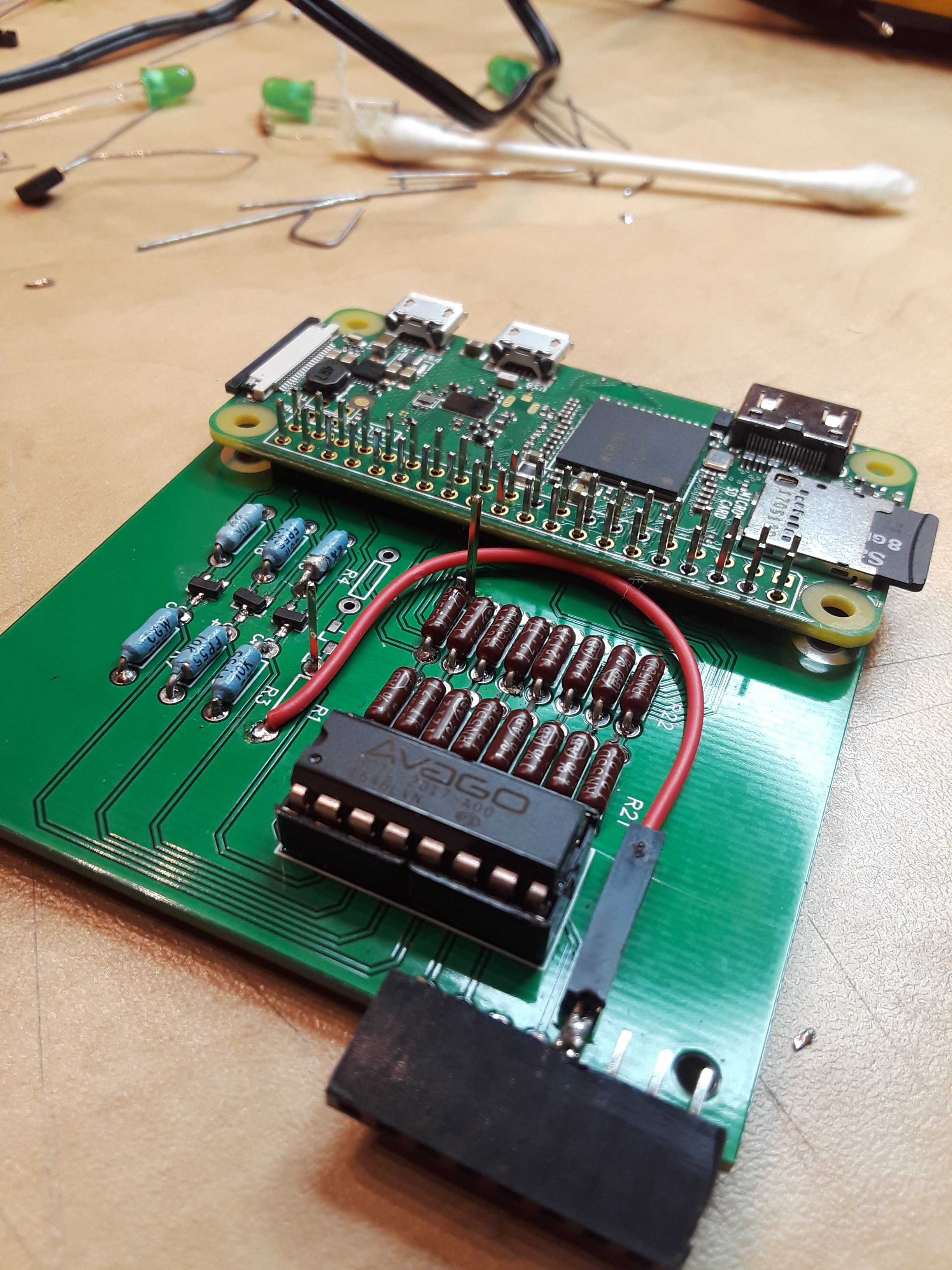
This circuit board reads the REF and MEAS signals from the interferometer. Those two signals are mixed in the quadrature counter, and a count of the number of times the signals wander in and out of phase appear as a 16-bit signed integer on the GPIO of the Raspberry Pi.
My python program is very simple.
- I'm using the ref_index library to determine the wavelength of my laser light
- the wavelength is dependent on the vacuum wavelength of my laser, and how the atmosphere manipulates the wavelength.
- a BME-280 humidity, temperature and barometric pressure sensor acts as my miniature weather station for the interferometer.
- Edlen's Equation is used to figure out how much the wavelength changed.
- The GPIO is used to control the HCTL-2017 quadrature decoder.
- the output of the decoder chip is the difference in wavelengths that the two light paths follow in the optics, relative to a starting position.
- Finally, the counter output is multiplied by the apparent wavelength of the laser light.
The output from the program is distance the moveable mirror moved. The units of measure are the same as the units used for the vacuum wavelength.
import ref_index

import Adafruit_BME280
import RPi.GPIO as GPIO

data_pins = [14, 15, 18, 23, 24, 25, 8, 7]
ctrl_pins = [16, 20, 21]
ctrl_seqs = [1, 1, 1, 2, 2, 2, 3, 3, 3]

GPIO.setmode(GPIO.BCM)
GPIO.setup(data_pins, GPIO.IN)
GPIO.(crtl_pins, GPIO.OUT)

sensor = BME280(t_mode=BME280_OSAMPLE_8, p_mode=BME280_OSAMPLE_8,  h_mode=BME280_OSAMPLE_8)

quadrature_count = 0
for ctrl_seq in ctrl_seqs:
     GPIO.output(ctrl_pins, [(ctrl_seq >> i) % 2 for i in range(0, 3)])
for i in range(0, 8):
     quadrature_count += GPIO.input(data_pins[i]) << i+8
GPIO.output(ctrl_pins, 5)
for i in range(0, 8):
     quadrature_count += GPIO.input(data_pins[i]) << i

temperature = sensor.read_temperature()
pressure = sensor.read_pressure()
humidity = sensor.read_humidity()
wavelength = ref_index.edlen(wave=632.6, t=temperature, p=pressure, rh=humidity)

distance = wavelength * quadrature_count
print(distance)
The decoder chip needs a clock input signal. To get this guy off the ground I'm using a 13 MHz clock generator IC, which plugs into the female connector on the printed circuit board.
As of this morning, I have the circuit board able to be powered up, and the GPIO controls are working. The 13 MHz clock is working too. I have pulled the quadrature counter out of it's socket and jumpered in, some bits into the input data bus, to let the code operate on those values.
To finish this circuit board;
- I need to clean up the codes associated with ctrl_pins in the python code above.
- wire in the REF and MEAS signals,
- I need to make sure I'm not killing the little power supply in the Raspberry Pi.
- I will have this accomplished in the next night or two.
To conclude, I'm happy to see that the circuit I designed is apparently going to be able to do what I wanted. I think I will have it wired to the interferometer today or tomorrow. However, while playing with the REF and MEAS signals and watching them carefully on my oscilloscope, It looks like the HP 5508A Measurement Display of the original interferometer, counts 1/6th of each wavelength of the quadrature signals. So that means that the design of my circuit board will only give me a fraction of the resolution I am seeking. I think my resolution is going to be on the order of ±50 ppm of an inch.
To skin this cat, I'm planning to add a set of Phased Locked Loops to the REF and MEAS signals. The PLL's will be used to multiply the frequency and phase of the two signals to a higher value, so that the phase count will have a higher resolution. While I'm designing PLL circuits, I figured, I'd use a third one to generate a clock frequency which will be derived from the laser's REF frequency. This way the clock will be in phase with the REF signal, and all of them will be derived from mixed laser frequencies.
Discussions
Become a Hackaday.io Member
Create an account to leave a comment. Already have an account? Log In.