For the logic functions, a Carry-out is generated just as for the ADD function. But the carry input is ignored because the relay RL1 is forced to an active or non-active state by inputs F2 and F3, so it is no problem that there might be a signal present on the Carry-out of the previous stage.
The simplest function to explain here is XOR:
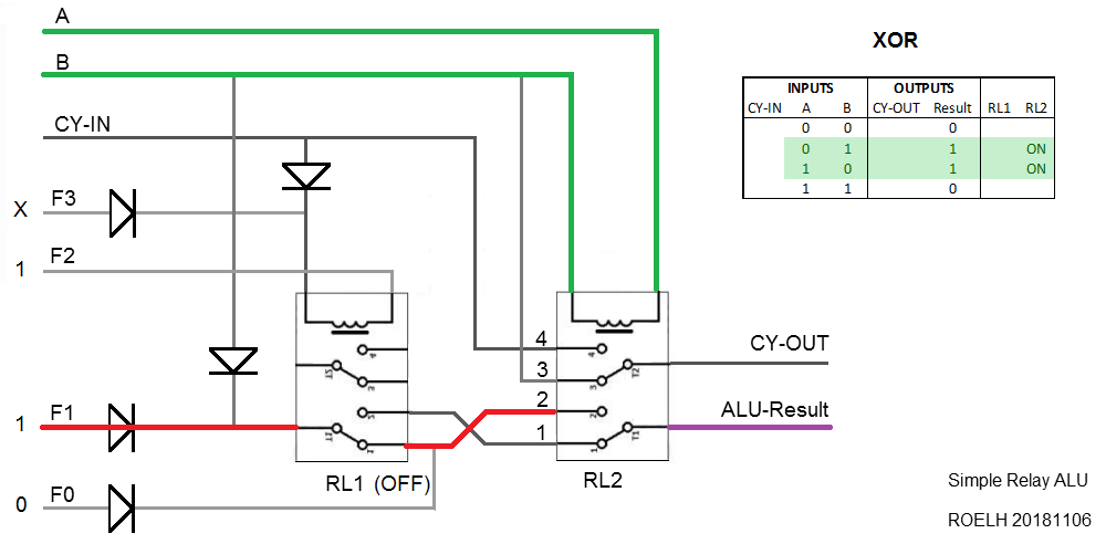
The control input F2 must be logic 1 (or floating). This ensures that RL1 is always off. If A differs from B, relay RL2 will connect the ALU-Result to the logic 1 provided by control F1. Otherwise, the result is not connected (meaning logic 0). The XOR function will be selected if either F0 or F1, or both are "1".
The next one is the XNOR function:
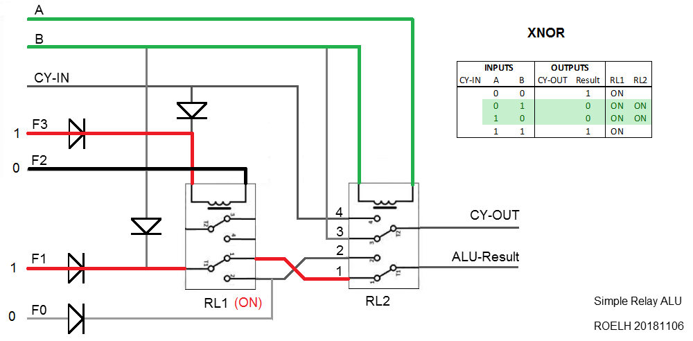
By making control input F3 active and F2 ground, relay RL1 will be always ON. Now, the ALU-result will be logic 1 when both inputs are equal, providing the XNOR function.
Now to describe the AND function:
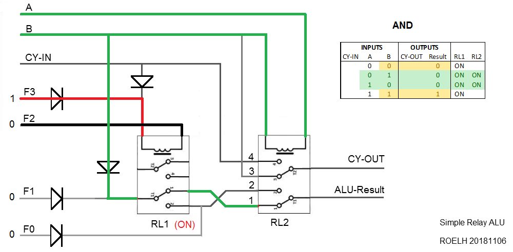
The only difference with the previous (XNOR) situation is, that control F1 is now 0. The result is, that the signal on input B now flow through a diode to connection 1 of relay RL2. The ALU result will only be one if RL2 is OFF (so both inputs equal) and input B is 1. So, it is only one if both A and B are 1.
The last function is OR:
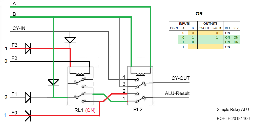
The only difference with AND is, that control F0 is now active. This causes an active ALU-result when A and B are different. When A and B are the same, the result is 1 if B is 1 (as in AND). Together, this delivers the OR function.
( The AND-gate, OR-gate pictures were taken from R. Lohberg and Th. Lutz: Hoe werkt een computer?, Kluwer (Netherlands) 1968. )
Discussions
Become a Hackaday.io Member
Create an account to leave a comment. Already have an account? Log In.