DeepSOIC
-
Remeasured DSP responses to include Connect+ effect
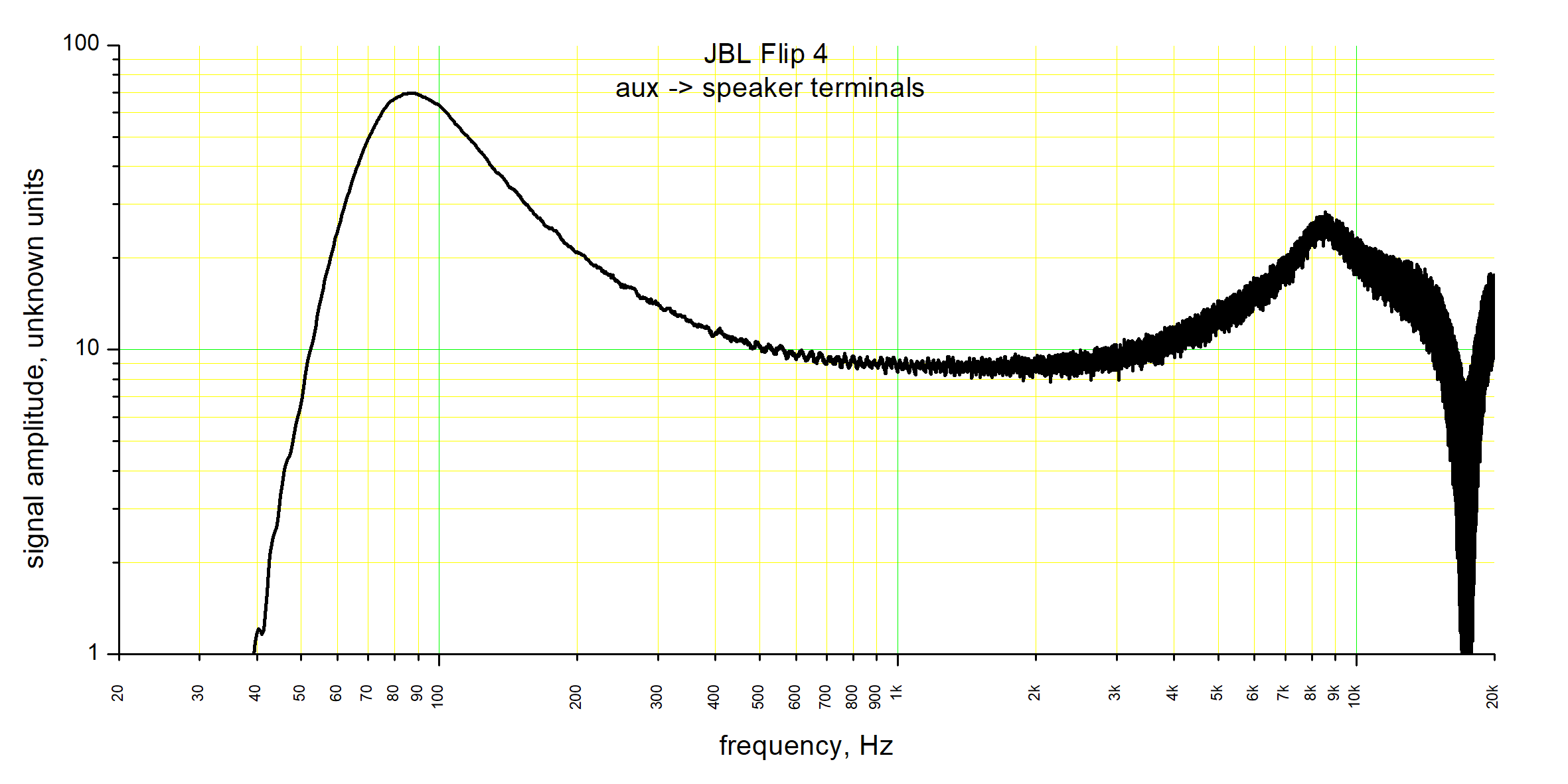
12/12/2018 at 21:17 • 0 commentsThe old graph only included standard DSP:
![]()
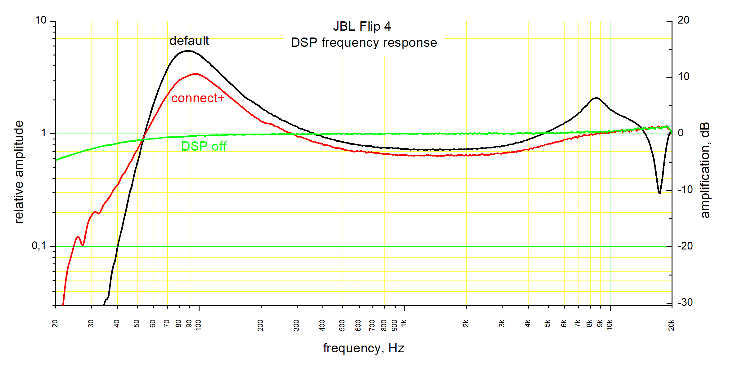
I remeasured it to include Connect+ button effect, and when DSP is off.
![]()
This time, I was taking signal from output of an opamp. That is, right before DC-rejection capacitor at power amplifier input. So overall response is for (DC-rejection caps on aux input) + (ADC) + (DSP) + (DAC) + (another cap) + (balanced-to-single-ended-converter circuit), and does not include (yet another cap) + (power amplifier).
Additionally, I disabled boost converter that powers the amplifier, to reduce noise.
I've also uploaded room-eq-wizard file to the project, so if you want to inspect it, go check it out in project files.
Measuring aux-to-air frequency response remains in to-do list.
-
How to fix audio dropouts through aux
01/27/2019 at 22:58 • 8 commentsThe speaker has an annoying habit of blocking aux sound when the signal is very low, causing annoying dropouts when playing quiet passages, watching movies and talking over skype.
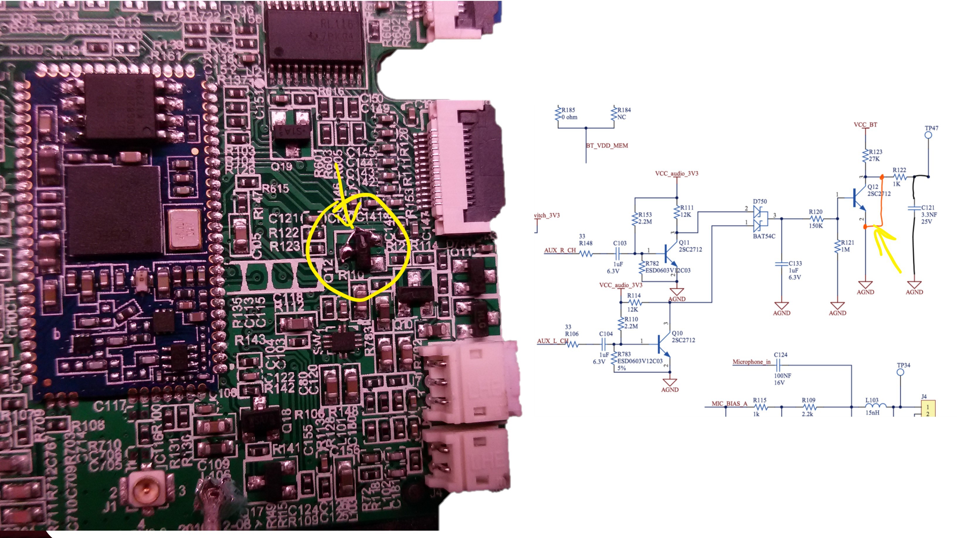
Guess what, the detection of audio signal is done in analog! so we can easily hack it, so that it thinks audio is always coming in.
![]()
It's just a matter of shorting out Q12 transistor's collector to emitter.
After doing this, I anticipated some problems with Bluetooth. There are, but they are minor.
+ I can still connect to BT, and pair new devices. The speaker doesn't make pairing sounds, though.
+ whenever Bluetooth plays, aux input is inhibited automatically. As soon as BT audio stops, aux input works again.
A nice hack! A better way would be to use jack to provide the signal whenever a cable is plugged in. It can be done, but requires desoldering the connector, and adding an additional connector to the board (or just permanently soldering a bunch of wires). But this easy one is good enough, IMO.
I also notice, input stage of this audio detector circuit presents serious nonlinear load to the audio source. This may cause distortion if source impedance is high. So, consider removing 33-ohm resistors if you apply this hack.
-
Got confused in amp powers
03/05/2019 at 20:29 • 0 commentsWhen I downloaded TPA3130 datasheet, I saw power figures of 2x50 W, and thought "wow, that's some serious margin there". And even published it here. Today I suddenly realized while re-reading the datasheet, that the datasheet is a shared one for 3 ICs: TPA3116, TPA3118 and TPA3130. The difference between them is their power rating (specifically, overload current limit).
The actual IC used here is only for 2x15 W.
Oops!
-
Driver data
03/07/2019 at 23:22 • 0 commentsMeasured using REW, by analyzing the change of impedance-vs-frequency plot when adding a known mass (1.34 g) to the cone.
Thiele-Small parameters
Rdc = 3.85 Ohm
fs 181.7 Hz
Qms 5.902
Qes 0.401
Qts 0.375
Fts 483.8
Mms 1.18 g
Cms 0.651 mm/N
Rms 0.228 kg/s
Vas 0.06 litres
Bl 3.615 Tm
Eta 0.09 %
Lp (1W/1m) 81.67 dB
Dd 3.22 cm
Sd 8.1 cm^2 -
contribution from karl.potratz
09/22/2020 at 11:15 • 0 commentsThanks to @karl.potratz for some extra data.
Software:
User Configuration Data 51 (Device Colour)
0001 = Black
0002 = Red
0003 = Blue
0004 = Turquoise
0005 = Grey
0006 = White
0007 = Red Base with Blue chequer crosses
0008 = Camouflage
0009 = Blue with Orange chequer stripes
000a = Grey with Turquoise chequer triangles
000b = Turquoise with Blue concentric square pattern
000c = Black
000d = Black
000e = Black
User Configuration Data 61 (Custom Device Name)
004a 0042 004c 0020 0046 006c 0069 0070 0034 0020 0031 0032 0033 0034 0035 0036
J B L F l i p 4 1 2 3 4 5 6
16 Chars max. (this can also be set via the JBL app)
Hardware:
2 different hardware/housing versions are available:
• New (from 2017?): Passive radiators are mounted via 5 screws, speaker grille has 3 round standoffs inside at the top. Flex print is open/visible.
• Old (up to 2016?): Passive radiators are held by housing and can be twisted off. All flex print is covered in black foam. Rubber gasket mounted between Speakers and housing.
Note: New and old speaker grilles and passive radiators cannot be interchanged!
Flat cable (Flex print)
• 1x FFC A 13 Pin 0.5mm pitch AWM (same side)
• 1x FFC B 6 Pin 0.5mm pitch AWM (opposite sides)
Reverse-engineering JBL flip 4
That is, full teardown, analysis, and hacking.