 Christoph
After some discussions in the hack/fpga chats I was able to come up with a PWM module that does what I wanted to do - in a simulation.
pwm_dn.v (the sync reset is subject to change)
module pwm #(
  parameter bits = 4
  )(
  input clkin,
  input reset,
  input[bits-1:0] max,
  input[bits-1:0] compare,
  output out
);

reg[bits-1:0] count = 0;
reg[bits-1:0] compareLatched = 0;

always @(posedge clkin)
begin
  if(reset == 1)
    begin
      count <= 0;
      compareLatched <= 0;
    end
  else
    begin
      if(count == 0)
        begin
          count <= max-1;
          compareLatched <= compare;
        end
      else
        count <= count-1;
    end
end
assign out = count < compareLatched;

endmodule
Regarding reset: there seems to be a lot of discussion about sync vs. async reset, and I haven't made up my mind about what I'd actually like. One thing that is pointed out regularly is that some FPGA prefer one over the other, behavior-wise. I don't know what the case is for the iCE40 series.
@Frank Buss pointed out this topic on stack exchange, which includes further reading:
https://electronics.stackexchange.com/questions/21696/reset-synchronous-vs-asynchronous
Then there's the assignment of out, which is not a register in the above code. A variant that was discussed is to assign the comparison result to a wire, and update that in the always block. This would make sure that it's always updated on a rising clock edge. However, it would also be delayed by one clock. All that probably doesn't matter for PWM which would usually be connected to some external device anyway.
The testbench, pwm_dn_tb.v:
`default_nettype none

module test;

reg clk = 0;
reg reset = 0;
wire out0,out1,out2,out3,out4,out5;

always #1 clk=~clk;

pwm #(.bits(3)) dut0(clk,reset,3'd7,3'd0,out0);
pwm #(.bits(3)) dut1(clk,reset,3'd7,3'd3,out1);
pwm #(.bits(3)) dut2(clk,reset,3'd7,3'd7,out2);
pwm #(.bits(1)) dut3(clk,reset,1'd1,1'd0,out3);
pwm #(.bits(1)) dut4(clk,reset,1'd1,1'd1,out4);

initial
  begin
    $dumpfile("dump.vcd");
    $dumpvars(3);
    reset = 1;
    #4
    reset = 0;
    #35
    $finish;
  end

endmodule
and some simulator output in gtkwave:
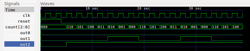
Reset is apparently handled correctly, the counters count down, and full-off and full-on work ok as well as intermediate values.
The other two dut's (for out3 and out4) are 1-bit devices just to see if the code even works with 1 bit resolution (on/off) - and it does.
So far I'm happy with this.
Discussions
Become a Hackaday.io Member
Create an account to leave a comment. Already have an account? Log In.