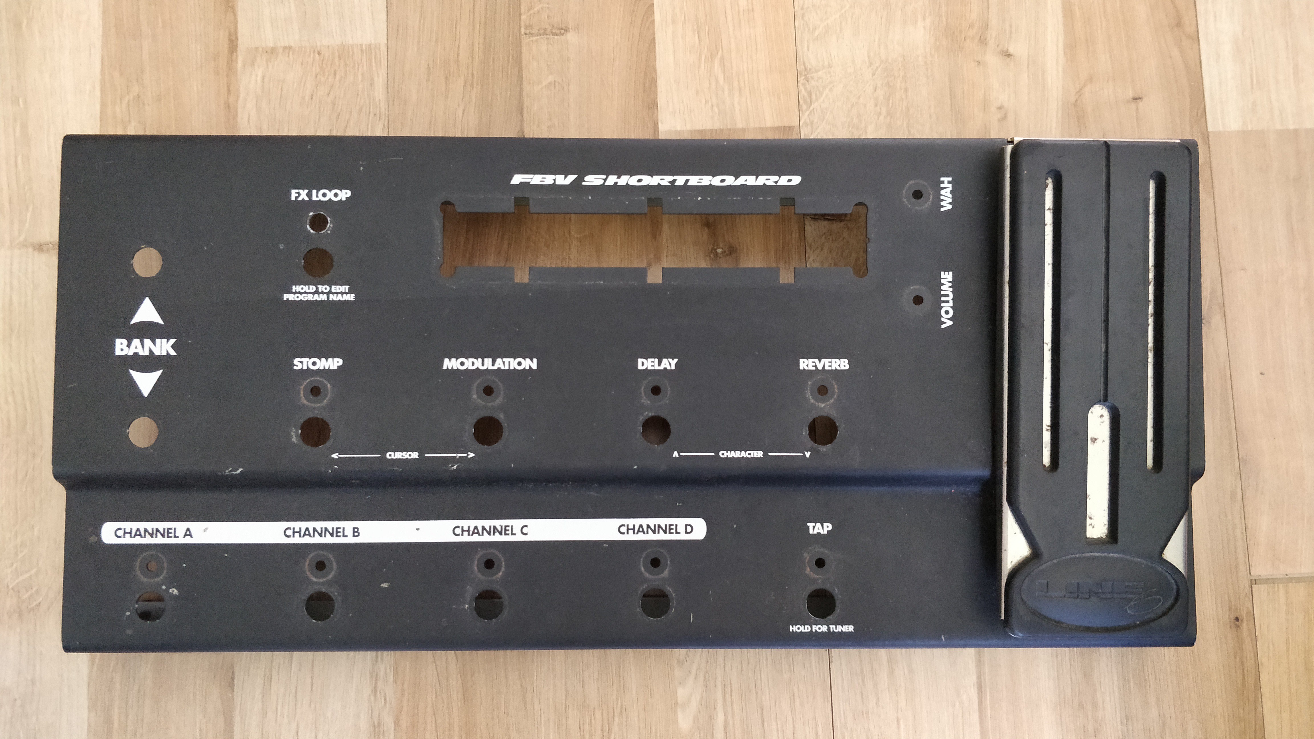
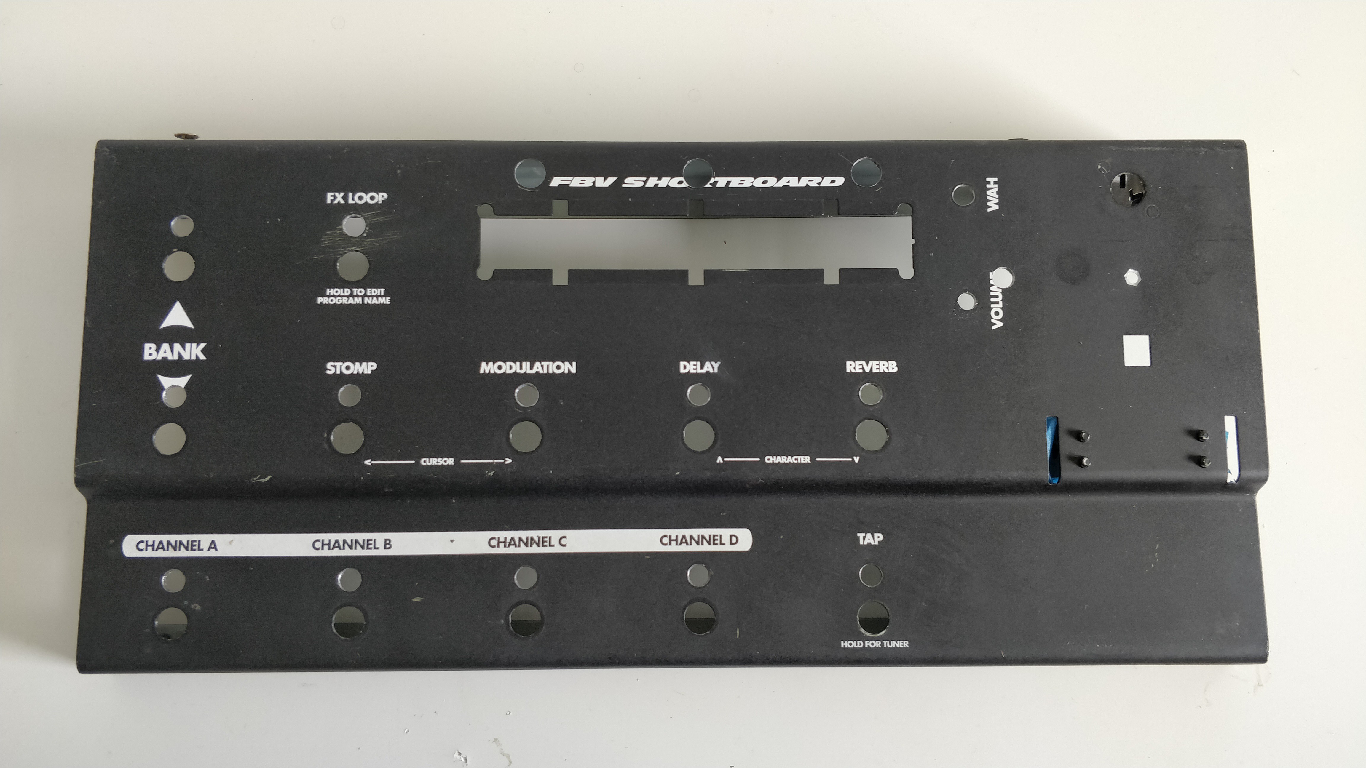
First task for the STJORN build was to rip the guts out of the Line 6 FBV Shortboard chassis. I wouldn't be re-using any of the internal components so out they all came. In hindsight I probably could have made use of the footswitches but prefer the 'non-clicking' ones I will be using.
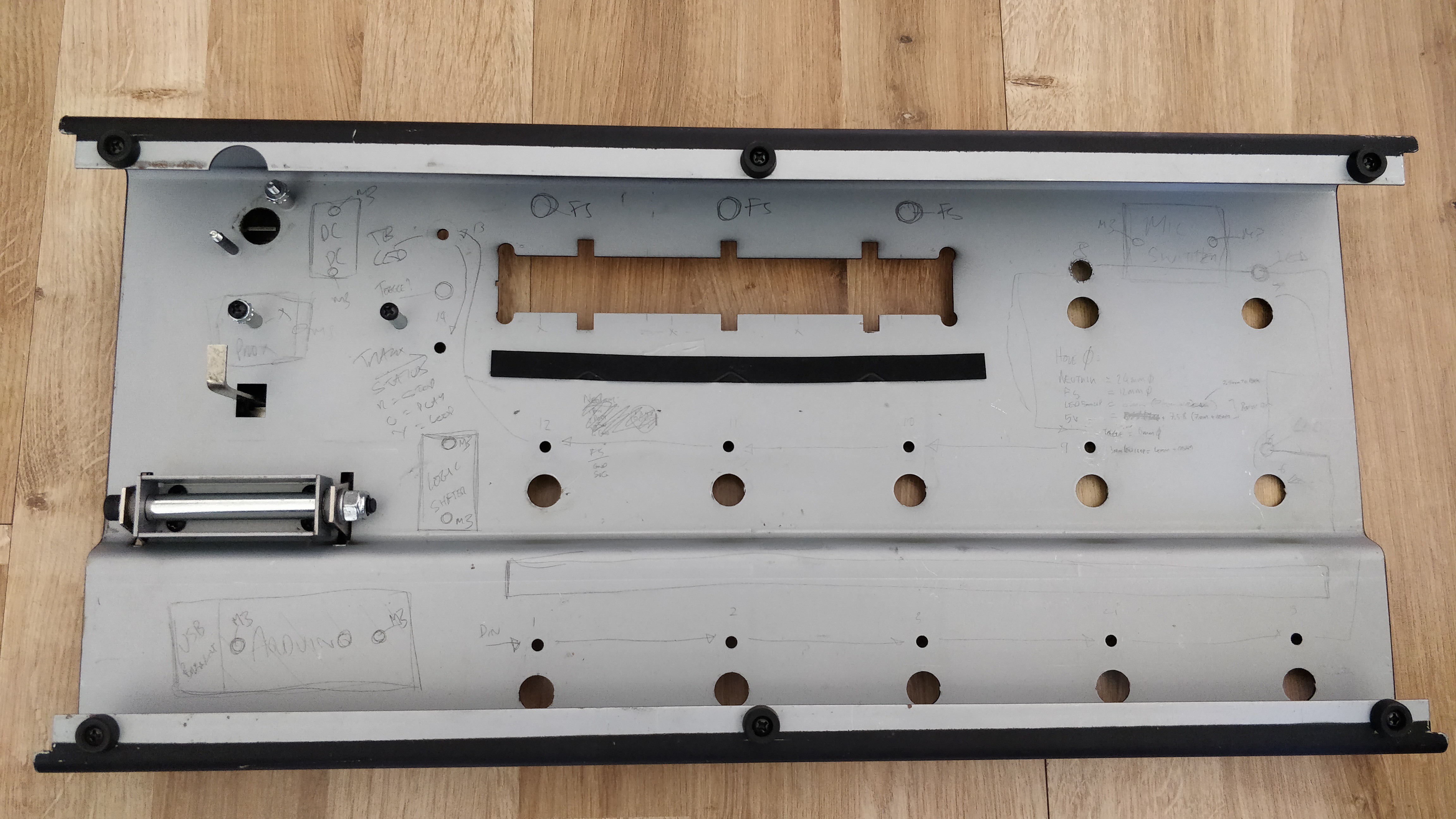
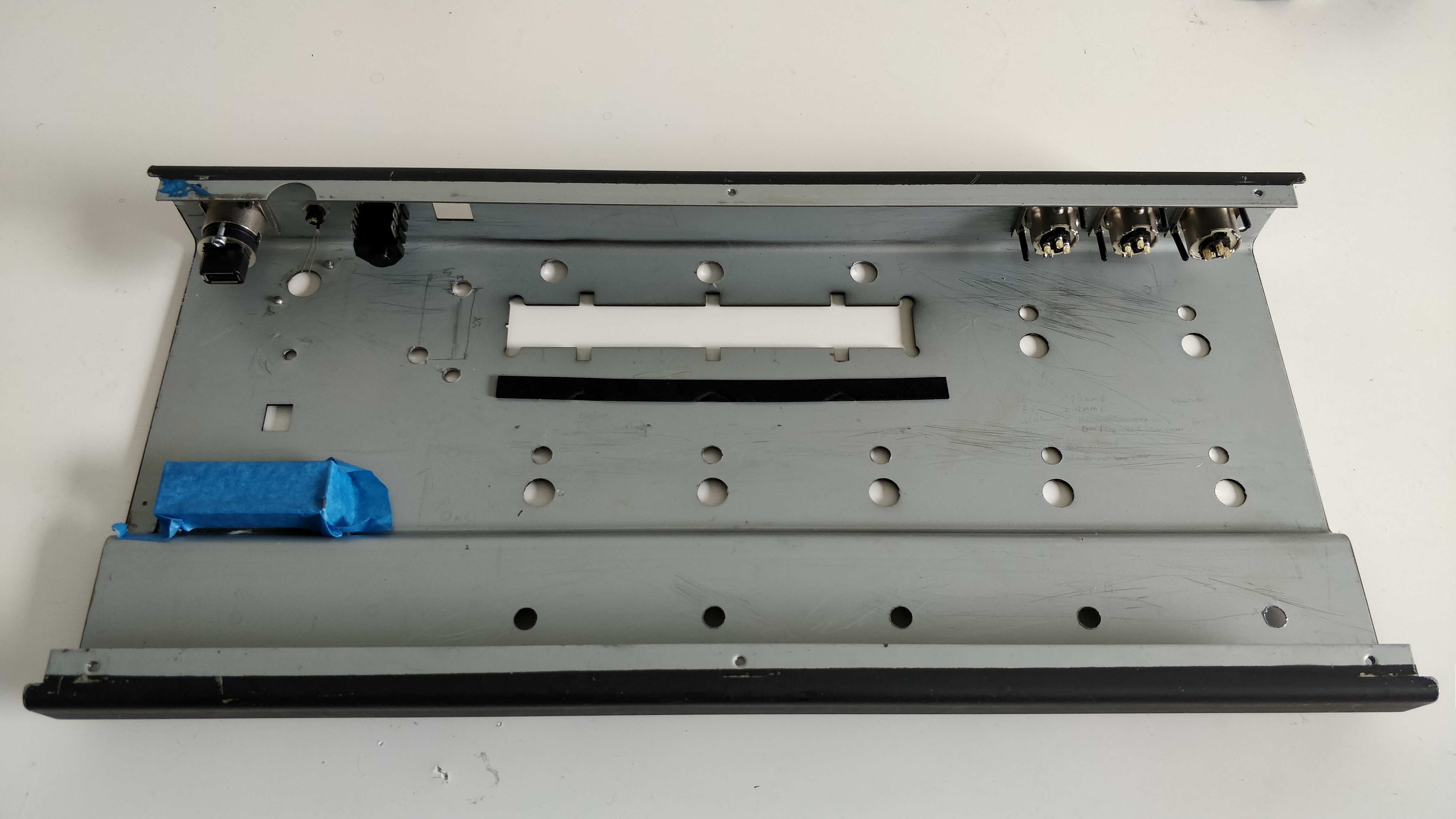
(Internal view showing some initial sketch thoughts of where components might be placed)
Step 2 was then to modify the chassis to accomodate the additional switches and sockets that I would be adding.
From the base chassis, the modifications I needed to make were:
- Drill holes for the three additional footswitches above the display
- Drill holes for the additional LEDs (one above each footswitch)
- Widen the current LED holes to accomodate 5mm through hole LEDs in sockets
- Remove the PCB standoffs
- Punch out the holes on the rear of the chassis for the XLR and USB Neutrik D size connectors
- Drill a hole on the rear for the DC power connector
Not a particularly large or arduous list but made even easier by two purchases I am very glad I made - a step drill bit and a Q-Max knockout punch.
Even though I have made various FX pedals and other similar projects in the past I have never invested in a step drill and have just used successively large drill bits to drill footswitch holes etc. Step drills are just so much better! Within literal minutes of marking up and centre-punching I had drilled all of the new footswitch and LED holes (I did use a 3mm drill as a pilot first) and enlarged the existing LED holes.
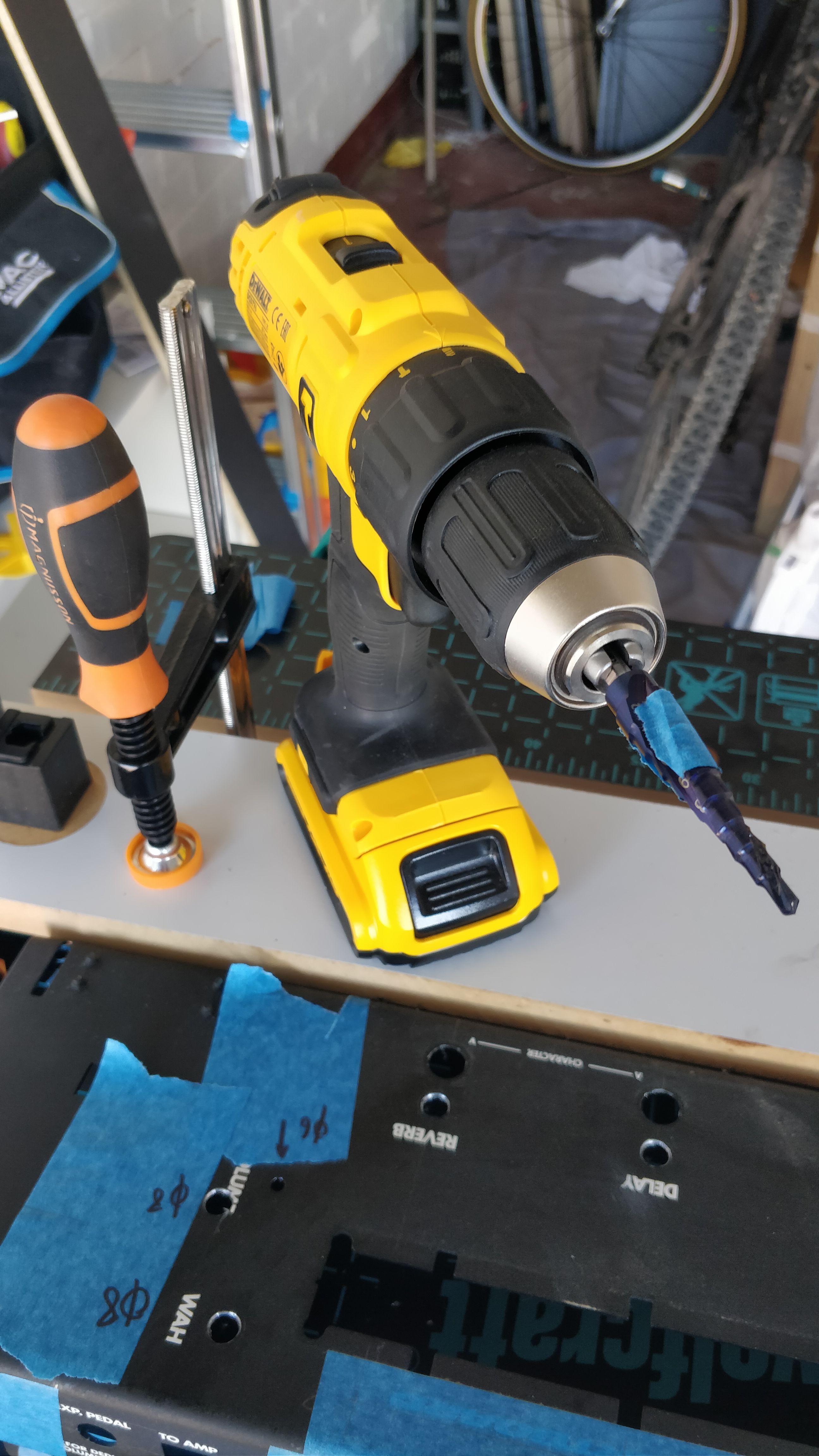
A quick once over with a hand-reamer and all the holes were good to go.
Next up was drilling the holes on the rear for the various connectors. The main ones were four Neutrik D sized connectors for the mic-switcher XLR sockets, and the main USB socket. Neutrik D connectors require a 24mm diameter hole for the main chassis and then 2off 3mm holes for the mounting screws. Second best purchase so far made this very easy - the Q-max knock-out punch.
Using the Q-max is a piece of cake - you simply drill a 10mm hole and then push the threaded part of the punch through. You then attached the cutting half of the punch to the other end and just tighten it with an allen key. The punch easily munches through the chassis leaving a perfect 24mm hole.
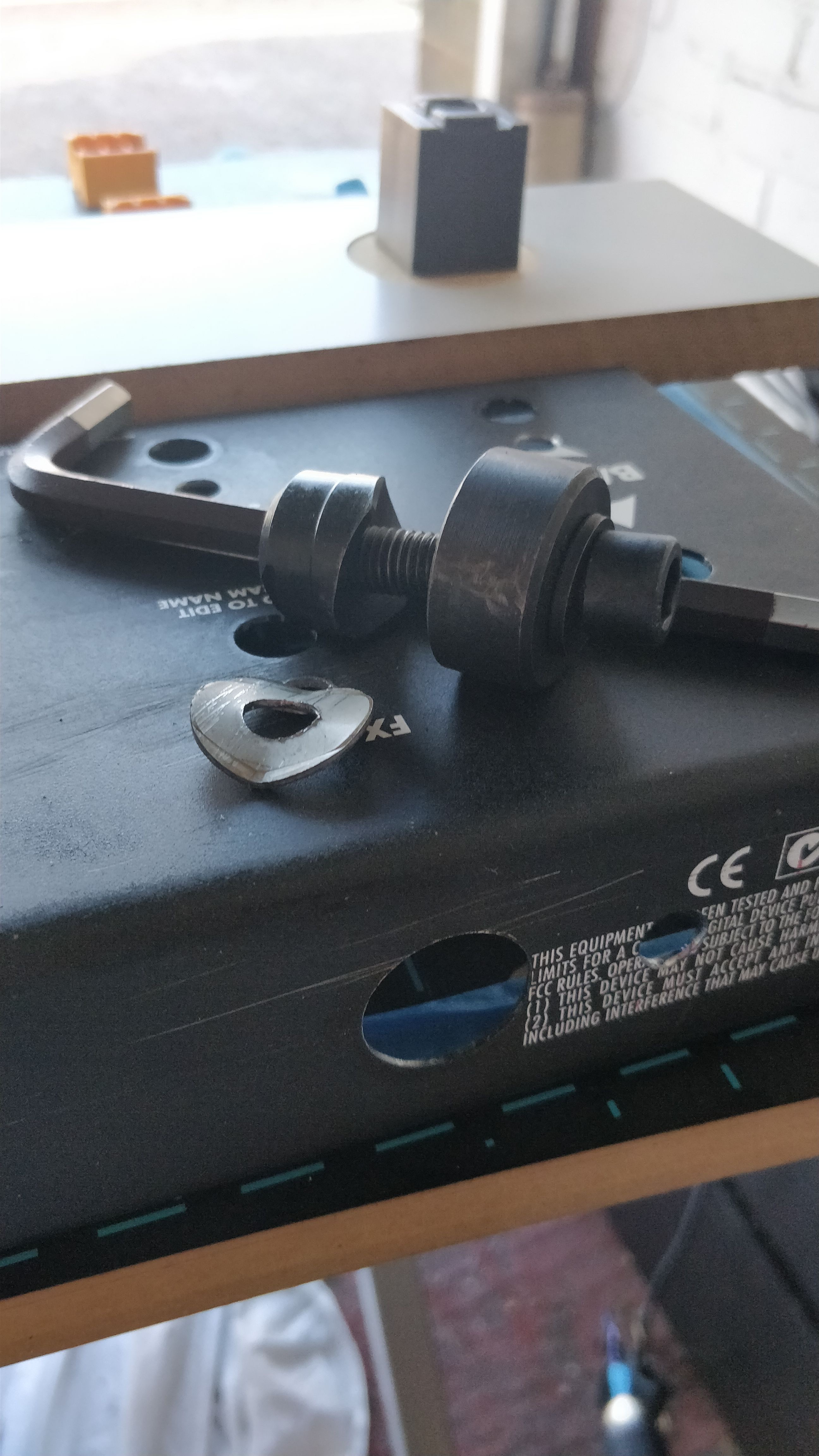
Four-off 24mm holes created in about 5 minutes - simple!
The only annoyance of this whole procedure was when I removed the PCB standoffs. I had a thought that I could just wrench them off the inside of the chassis with brute-force and ignorance. Sadly the latter part of that phrase came in to play when I realised that doing so now left a hole in the top of the chassis...
However, I turned an annoyance in to something useful and drilled out the small hole to accomodate another LED - I had actually removed one of the LEDs from teh design when I decided to add a rotary encoder in it's place and fortunately the accidental hole was right next to where the encoder would sit and provides a good location to have another LED. So disaster averted.
I test fitted the rear chassis hardware and everything fits great so on to the next stage - painting!
(The additional, accidental, hole can be seen to the right of the screen cutting in to the word 'volume')
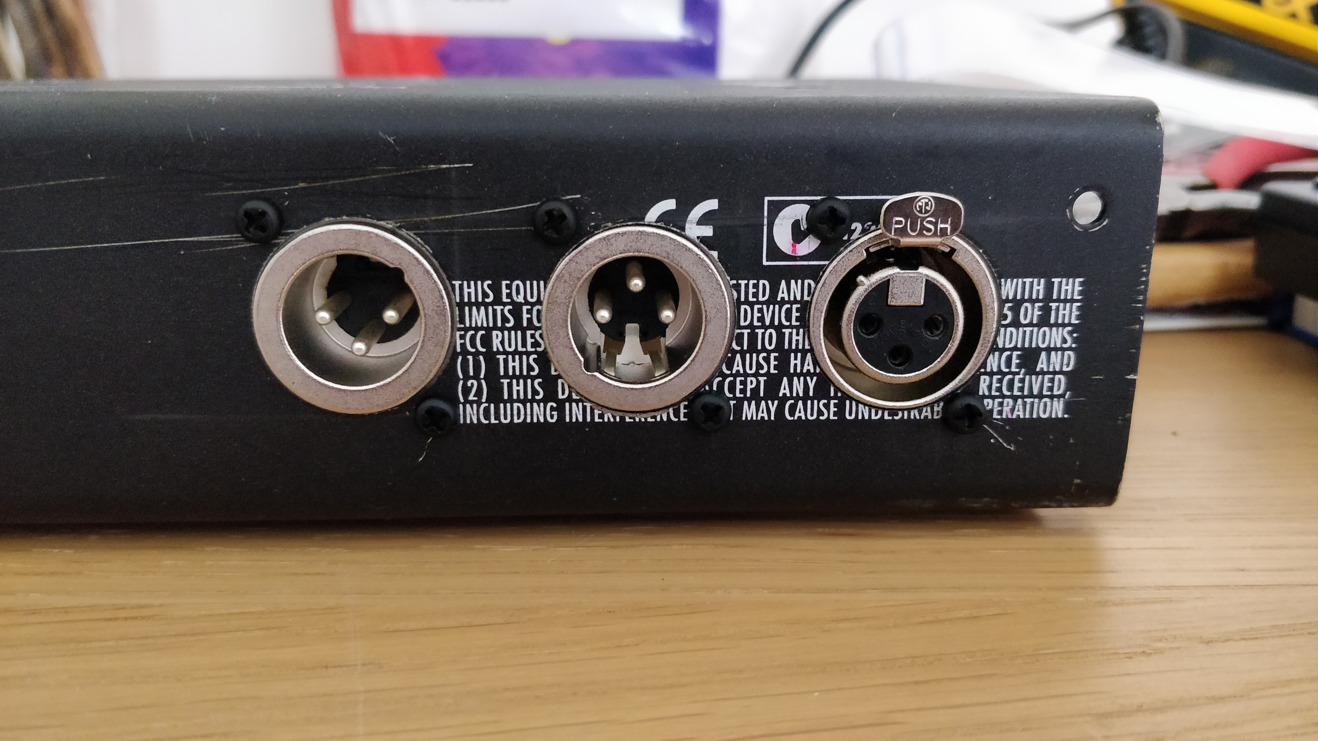
(The Neutrik D XLR connectors - and yes I realise I have one inverted....)
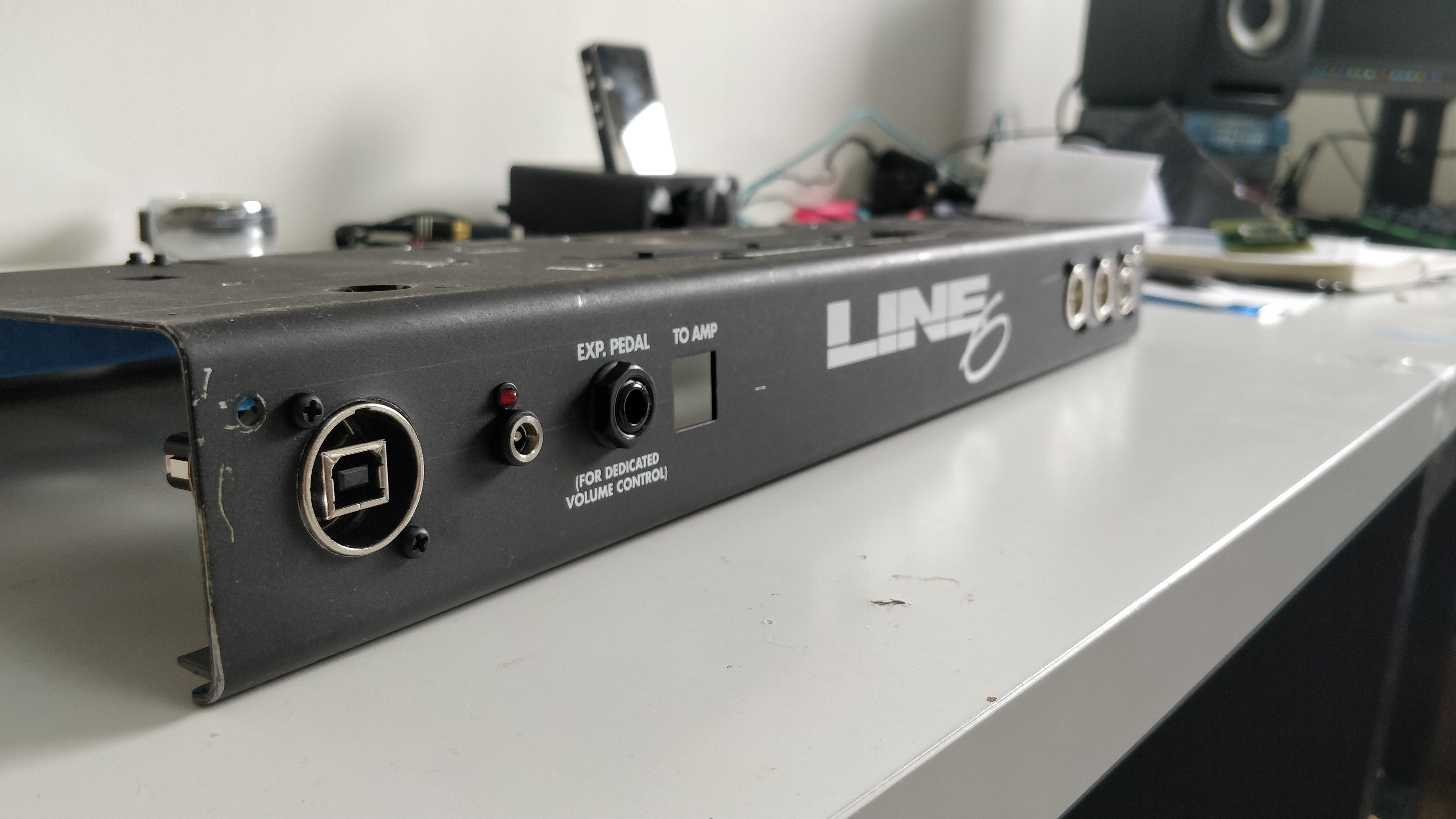
(USB, power, and external expressions jacks - the expression jack hole was actually already there. The square hole previously had the Line 6 RJ45 connector to go to the amp it was controlling, this slot will now also have an RJ45 socket in it which is part of the Qwiic i2c differential breakout to act as an 'extension' socket)
Discussions
Become a Hackaday.io Member
Create an account to leave a comment. Already have an account? Log In.