i2c - along with SPI - are two protocols that allow communication between controllers. I2c (inter-integrated-circuit; it’s pronounced I-squared-C I believe) is a simple to use protocol allowing two way communication between a master device and multiple minion devices. These devices can be any sort of circuits - sensors, actuators, even other Arduino’s - and each can receive data from or send data to the master device. All this is achieved with just two wires; a data line and a clock line.
As already mentioned in the project log on the displays chosen for this project, I had chosen to use Adafruit’s 14-segment alphanumeric backpacks which communicated with the micro-controller using i2c. As such I was already setting up an i2c bus and so it was easy to integrate some more devices in to STJORN.
Proximity Sensor
One of the main reasons I went for the Line 6 enclosure is that it had a built in expression pedal, meaning I didn’t have to drag along a separate unit when I wanted volume or Wah control. I had, perhaps naively, assumed this was controlled with a potentiometer of some sort, but on opening the Line 6 controller up I discovered it actually used an IR based proximity sensor. Initially I tried to work out if I could somehow rig the pedal up mechanically to a potentiometer but after realising that could end up quite complex, I started to look for a way of using a sensor instead. My first though - coming from an automotive engineering background - was possibly a Hall effect sensor with a magnet mounted to the proximity ‘arm’ on the back of the expression pedal. This would undoubtedly have worked, but my searching lead to a better solution - Adafruit make an IR based proximity sensor board which would essentially replicate what the pedal was already designed for.
This board incorporates the IR LED, the receiver, plus all the associated electronics to send the data from the receiver over i2c to the micro-controller. Along with the library that goes with it, this means that in the program it is simply a case of requesting the current proximity and you get a nice, unitless, value back to work with. Easy peasy.
Rotary encoder
This was a very last minute addition when, on removing the PCB standoffs from the Line 6 enclosure, I inadvertently made an ‘additional ‘ hole in the enclosure,... The hole was fortuitously located and so I decided to fill it with a rotary encoder. I had previously thought about having some sort of menu system and with the addition of the encoder this would be possible.
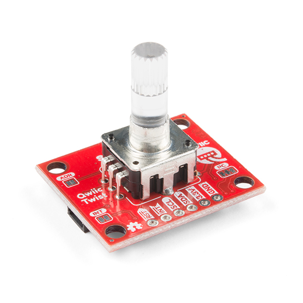
The encoder I chose was the Sparkfun Qwiic Twist. This little board mounts an ‘endless’ rotary encoder which incorporates a push button (by pushing down on the encoder knob) and also an RGB LED so that, along with a clear knob, the encoder can also be used to display information in colour.
All of this connects over i2c and the associated library spits out how many ‘ticks’ the encoder has moved so that readings can be made easily, and allows very simple control over the RGB colour.
The ‘Qwiic’ part of the name of this board refers to a connector system Sparkfun use - it is a very small, push fit connector - you can just see on the right of the board above - that can be used to link multiple boards by carrying the data, clock, ground, and power between them. The board also incorporates normal solder points for these signals, but the connectors make it very easy to use, especially for prototyping.
I2C Differential Breakout
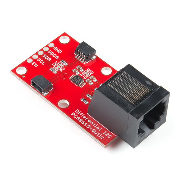
This, again, was a last minute addition and came about by accident whilst browsing through Sparkfun’s ‘Qwiic’ catalog after choosing the encoder board above. Having an RJ45 shaped hole in the STJORN enclosure I had nothing to fill with the sight of an RJ45 connector sparked my interest. On closer investigation this little board would open up some great expansion possibilities.
That board is Sparkfun’s i2c differential breakout and what it does is take the i2c data and clock signals and ‘convert’ them to differential signals that can be sent over CAT5/6 cable. Standard i2c has a very short maximum distance it can send and receive data as it is designed for commas between circuits within a particular unit. By converting to a differential signal and sending over Cat5 to another of these circuits in another device allows two devices to communicate with i2c but at distances of hundreds of feet from each other.
Although this wouldn’t immediately add anything to the STJORN controller, I have some uses for it which could really expand the possibilities of this controller:
‘Remote’ control - Where I will be using STJORN most, it is often useful for another member of the band to be able to have control over clicks and tracks. By using this device to link to another, simpler, foot controller, this ‘remote’ can send signals to STJORN via i2c and be able to control in the same way STJORN does. As the communication is bi-directional it also means statuses can be sent back the other way. This is a really exciting possibility for my use case and will be the next thing to be developed!
FX Switcher - another possible use is to hook STJORN in to a remote FX switching system. The receiving device would be a set of relays allowing switching in and out of analog FX units in to the signal path going to the audio interface. As the range of the i2c comes using this board is long, the FX switching board could be located close to the interface rather than having to take up floor space on stage.
MIDI converter - a very simple one, but this port could be used to add MIDI I/O to STJORN. This is already present in some way on the audio interface I use, but by incorporating it in to the STJORN controller means that external MIDI can be processed by STJORN before it is sent on to my laptop (or wherever). A device such as this could also be used to turn any MIDI capable controller in to a ‘remote’ as described above.
Nothing firm for the use of this yet and, at minimum, it just fills a hole in the enclosure - but hopefully interesting things to come!

Discussions
Become a Hackaday.io Member
Create an account to leave a comment. Already have an account? Log In.