 Amos
Amos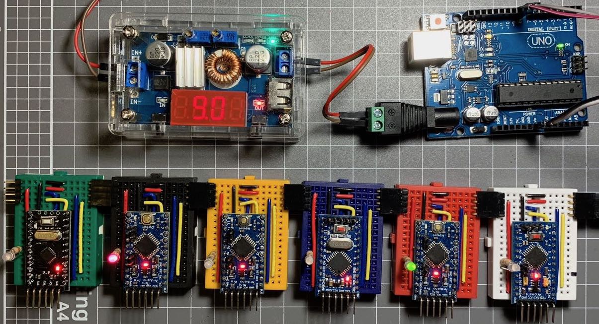
Having decided on serial communications for the blocks, I now need to devise a protocol so the blocks can communicate with each other and the master controller. What follows is some of the reasoning I used in devising the protocol I ended up using.
The Commodore 8-bit computers used a serial bus for their peripherals. Each device had two serial ports - the first device would be connected to the computer via one port, and the next device would be connected to the first via the first device's second port. Each subsequent device would be similarly connected to the previous device's second port, giving a long chain of connected disk drives and/or printers. Commodore's solution to identifying devices was to give each device a device id (sometimes set using DIP switches) which allowed for a small number of devices on the bus. (The address ranges used allowed for two printers, one (or two?) plotters, up to eight disk drives and a handful of other devices.) Hard-coding device ids won't work for a programming language (even with DIP switches) so I will need another way of identifying blocks, but the serial topology is a definite possibility.
One drawback with this design is that I need two serial ports and the Arduino Pro Mini only has one serial port available (on pins D0 and D1) so where to find an extra serial port? For that I turned to Paul Stoffregen's AltSoftSerial library. This allows you to add an extra software controlled serial port to your Arduino and should give me the extra port I need. On the upside, I would only need four wires connecting each block (power and ground and RX and TX) which would make for a neat layout.
The next thing I needed to do is determine some way of identifying blocks on the serial bus and for that I looked to the WS2812 LEDs. I discovered that you can purchase WS2811 ICs, which are the same as the chips in the WS2812 LED packages and I thought they might prove useful. For the longest time I tried to find a way to use the Worldsemi WS2811 IC to handle the serial communications, but I killed that idea as the WS2811 is designed for LEDs and only outputs three analog signals (one each for red, green and blue channels) where I needed a digital value. So I needed to come up with my own protocol.
Apart from the analog output, another problem with the WS2811 IC protocol is that to send a message to a specific device, you need to send data for every device in between you and the target. Each device in the chain gobbles up three bytes of data. To send a signal to the 10th device in the chain, you need to send 30 bytes of data (three bytes for each device). So while WS2812 LEDs are touted as individually addressable, they really aren't - you need to output the RGB values for every LED in the strip each time you want to change the colour of a single pixel. I wanted a truly individually addressable protocol...
My first, simplistic approach was to use relative addressing. Instead of assigning a unique id or address for each block, what if I used relative addressing? So instead of an absolute address, use the number of "hops" between you and the device you want to send the message to. To send a message to the next block, use an address of 0. The block after that is address 1, the one after that is 2 and so on. When receiving a message, each block will look at the destination address of the message and if the destination is 0, then it must be for you. If it is greater than 0, decrement the address and forward it on to the next block in the chain. There may be times when you need to send a broadcast message and blocks need some reliable way of communicating with the control unit, so why not use a coupe of special reserved addresses for this? 255 can be a broadcast id - if a block receives a message addressed to 255, then the block must act on that message and forward it without decrementing the address. Similarly, if the address is 254 it is for the control unit, so it is forwarded up the chain, again without decrementing the address.
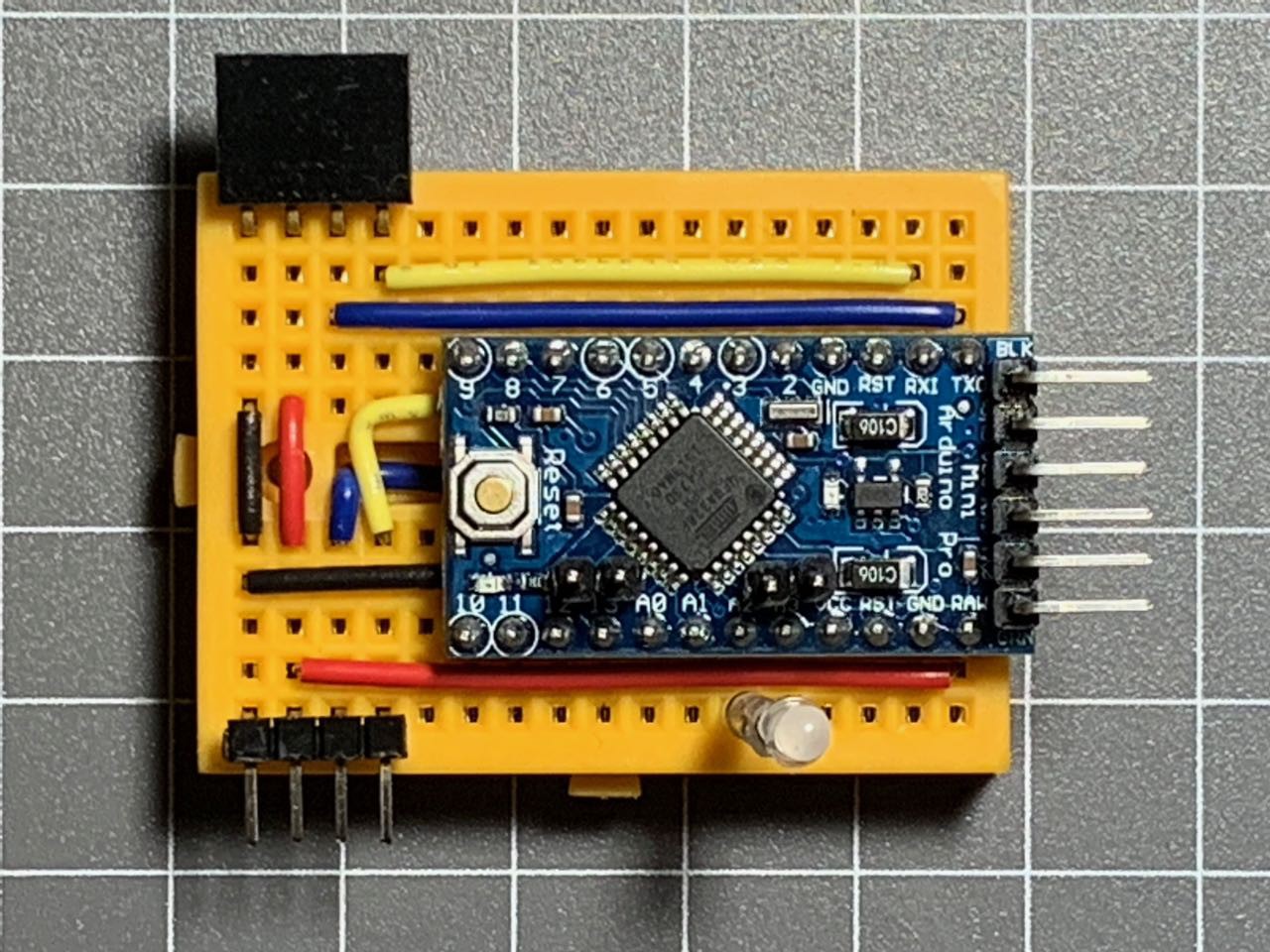
So I decided to see if I could get this relative addressing scheme working. I decided on the convention of connecting the hardware serial port (pins D0 and D1) to the "upstream" (i.e. going towards the control unit) and the AltSoftSerial port (pins D8 and D9) heading "downstream" (i.e. "away" from the control unit). For this initial test, I would only implement sending messages from the control unit "downstream" with no replies coming back from the blocks. Blocks will only forward messages (if required) downstream and not back towards the control unit. (For now.) I wired up some blocks (as seen above) with a red/green LED on pins A2 and A3, so I could toggle between red or green display. I decided that for now the message would be a single byte which would tell a block to either light the RED LED, the GREEN LED or to turn the LED off.
The initial setup code (identical for the control unit and the blocks):
#include <AltSoftSerial.h>

AltSoftSerial altSerial;

// Set some GPIO pins for LEDs
#define BICOLOUR_RED A2
#define BICOLOUR_GRN A3

// Some message constants
#define LEDS_OFF 0
#define RED_ON 1
#define GREEN_ON 2

#define BROADCAST_ID 255

void setup() {
  // put your setup code here, to run once:
  Serial.begin(9600);
  altSerial.begin(9600);
}
Sending a message is simple:
// Sends a numeric message over a number of hops (0 means the message is for the next in the chain)
void sendMessage(int hops, int mesg) {
  altSerial.write(hops);
  altSerial.write(mesg);
}
Note: This is a simple proof of concept, so I am not worrying about start or end message indicators and error checking? Who needs error checking? ;^)
For the blocks, the loop() is just waiting for a message on the Serial port, which it interprets as the first byte being the address and the second byte the message. If the message is addressed to block 0 or 255, the appropriate LED is lit, if not the message is forwarded.
void loop() {
  if (Serial.available()) {
    // read the incoming byte:
    int hops = Serial.read();

    // Wait for another bit of data...
    // Not really good practice, but let's roll with it for now...
    while (Serial.available() == 0) {}

    int msg = Serial.read();

    switch (hops) {
      case BROADCAST_ID:
        forwardMessage(hops, msg);
      case 0:
        switch (msg) {
          case RED_ON:
            digitalWrite(BICOLOUR_GRN, LOW);
            digitalWrite(BICOLOUR_RED, HIGH);
            break;
          case GREEN_ON:
            digitalWrite(BICOLOUR_RED, LOW);
            digitalWrite(BICOLOUR_GRN, HIGH);
            break;
          case LEDS_OFF:
          default:
            digitalWrite(BICOLOUR_RED, LOW);
            digitalWrite(BICOLOUR_GRN, LOW);
        }
        break;
      default:
        hops--;
        forwardMessage(hops, msg);
        break;
    }
  }
}
Note: Again, there is no error handling at all here and the code is far from production quality, but if it works I know I can continue down this path...
So with that code (or something very similar) loaded onto the blocks (Pro Minis) I decided to test it out. The control unit for this test was an Arduino Uno, and I set up a simple loop that told the blocks to flash their LEDs in a bit of a pattern like so:
  sendMessage(BROADCAST_ID, RED_ON);
  delay(500);

  sendMessage(BROADCAST_ID, GREEN_ON);
  delay(500);

  sendMessage(BROADCAST_ID, LEDS_OFF);
  delay(500);

  for (byte i = 0; i < NUM_BLOCKS ; i++)
  {
    sendMessage(i, RED_ON);
    delay(500);
    sendMessage(i, LEDS_OFF);
  }

  for (byte i = NUM_BLOCKS - 1; i > 0 ; i--)
  {
    sendMessage(i, RED_ON);
    delay(500);
    sendMessage(i, LEDS_OFF);
  }

  for (byte i = 0; i < NUM_BLOCKS; i++)
  {
    sendMessage(i, RED_ON);
    sendMessage(NUM_BLOCKS - i - 1, GREEN_ON);
    delay(500);
    sendMessage(i, LEDS_OFF);
    sendMessage(NUM_BLOCKS - i - 1, LEDS_OFF);
  }
  for (byte i = 0; i < NUM_BLOCKS; i++)
  {
    sendMessage(i, GREEN_ON);
    sendMessage(NUM_BLOCKS - i - 1, RED_ON);
    delay(500);
    sendMessage(i, LEDS_OFF);
    sendMessage(NUM_BLOCKS - i - 1, LEDS_OFF);
  }
Again, not pretty, but if it works, it works.
And the proof is in the pudding...
Discussions
Become a Hackaday.io Member
Create an account to leave a comment. Already have an account? Log In.