Close
0%
0%

MSP430F5529 Interrupts, Timer, and 60 second Count

Using MSP430 to have a Seconds Counter with the help of inbuilt TIMER-A and Hardware interrupts to keep track on number of counts.

Similar projects worth following
2.2k views
0 followers
Welcome!
Making of Seconds Counter:

Using CCStudio 8 and MSP430F5529 for the project.

Using C language to code the micro controller.

Apply Low Power Modes, Timers and Interrupts.

ISR are defined with pragma vectors in C language.

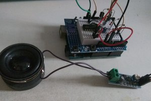
The output is displayed via 7 Segment.


Any MSP model can be used but should take care of the syntax during implementation.

Activate inbuilt peripherals like hardware interrupt and timer.

The ISR runs the code which has to be performed when the interrupt arises.
Timer ISR is used to make a precision counting of 1 second delay. This is more efficient then a for loop in a micro controller, as the CPU is not running this operation , the Timer module does.
There by saving power while the timer works in Low Power Mode.

And the output coding for 7 segment is stored in an array and called.

Can find the related material on Seconds Counter file in my repository 
https://github.com/vivekadi/MSP430

  • 1 × MSP430F5529 Ti Launchpad Microprocessors, Microcontrollers, DSPs / ARM, RISC-Based Microcontrollers
  • 2 × Common Cathode 7 Segment Display Display element
  • 2 × Voltage drop resistors of 200 Ohms Passive component
  • 1 × Button Switch (not required if inbuilt) External accessory

  • Port Initialization

    Adi Vivek12/11/2018 at 19:57 0 comments

    Now lets look at how to use the pins for output.

    There are many ports on the MSP430 (varies on version) , for example PORT-1  ( P1.0 to p1.7 ) & 

    PORT-2 ( P2.0 to P2.7 ).

    #include <msp430.h> 
    
    
    /**
     * main.c
     */
    void main(void)
    {
    	WDTCTL = WDTPW | WDTHOLD;	// stop watchdog timer
    
    	 P3DIR=0xFF;                    // P3DIR=0x00;
             P6DIR=0xFF;
    
             P4DIR |=0x00;
             P4REN |=0xFF;
             P4OUT |=0xFF;
    
    }
    

     P3DIR |=0x00 tells us that the whole of PORT-3 is initialized to take inputs.

    P3DIR |=0xFF tells us that the whole of PORT-3 is initialized to give outputs.

    P3DIR |=0x01 only the pin P3.0 is initialized to output in PORT-3.

    This follows a Hexadecimal Port mapping.

    The Major advantage with the higher versions of MSP430 are , they have inbuilt Pull -Up or Down resistors, so no need to connect externally.

    P4REN |=0xFF , this indicates that the pins of PORT-4 have their pull up/down resistors enabled.

    TO select them between Pull UP or Pull DOWN, the instruction P$OUT |=0xFF is used.

    If 0xFF is used they configure as Pull UP resistors and if 0x00 they configure as Pull DOWN. 

  • INSIGHTS

    Adi Vivek12/11/2018 at 19:39 0 comments

    Let's Begin!

    Initialize the watchdog timer to OFF state using the required password for the watchdog timer

    (It helps to keep check of infinite loops , keeping the processor safe).

    #include <msp430f5529.h>         // or #include <msp430.h>
    
    
    /**
     * main.c
     */
    int main(void)
    {
    	WDTCTL = WDTPW | WDTHOLD;	// The HOLD bit is 1
    	
    	return 0;
    }

    WDTCTL is the watch dog timer control register. 

    One of the Bit is WDTHOLD , this can be accessed through a specific password value WDTPW.

    From WDTHOLD one can control ON and OFF of a Watchdog timer.

View all 2 project logs

Enjoy this project?

Share

Discussions

Similar Projects

Does this project spark your interest?

Become a member to follow this project and never miss any updates