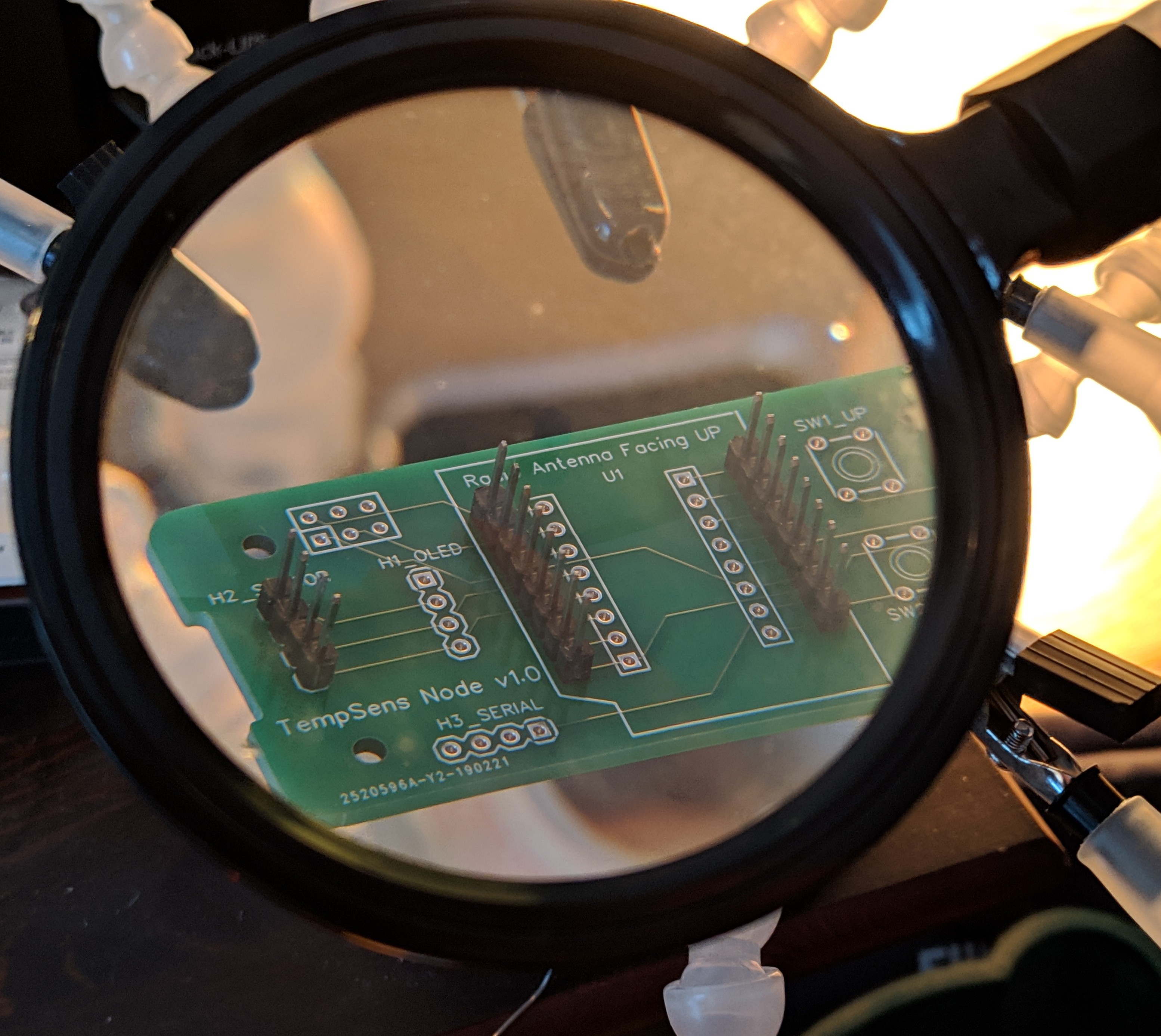
First I take a blank PCB and put 1x4 header in the BME position and two 1x8 headers in the outer ESP8266 mounting positions
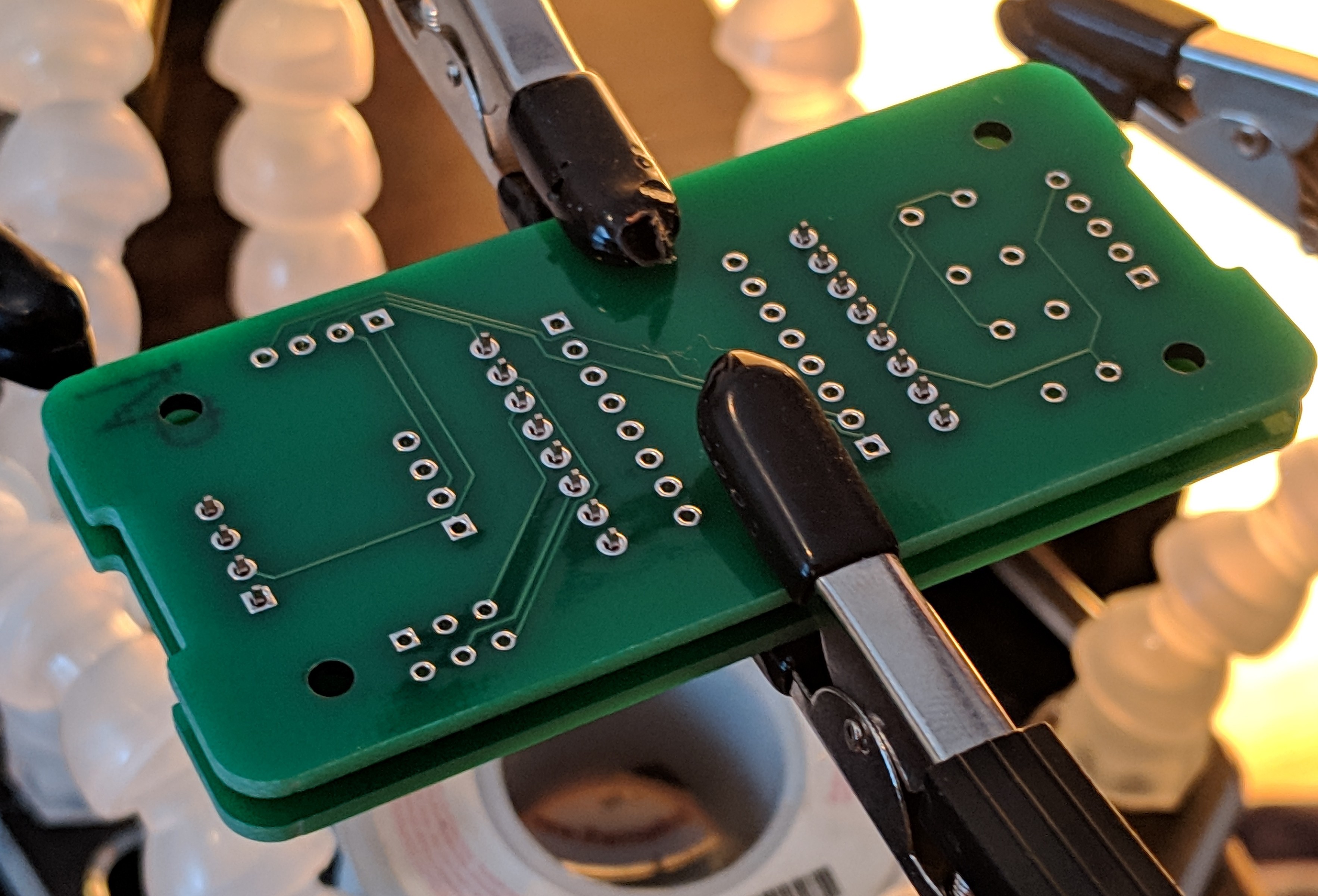
Next I place another blank PCB over to make a sandwich, keeping the loose headers in alignment, then flip the combination over to solder the bottom side.
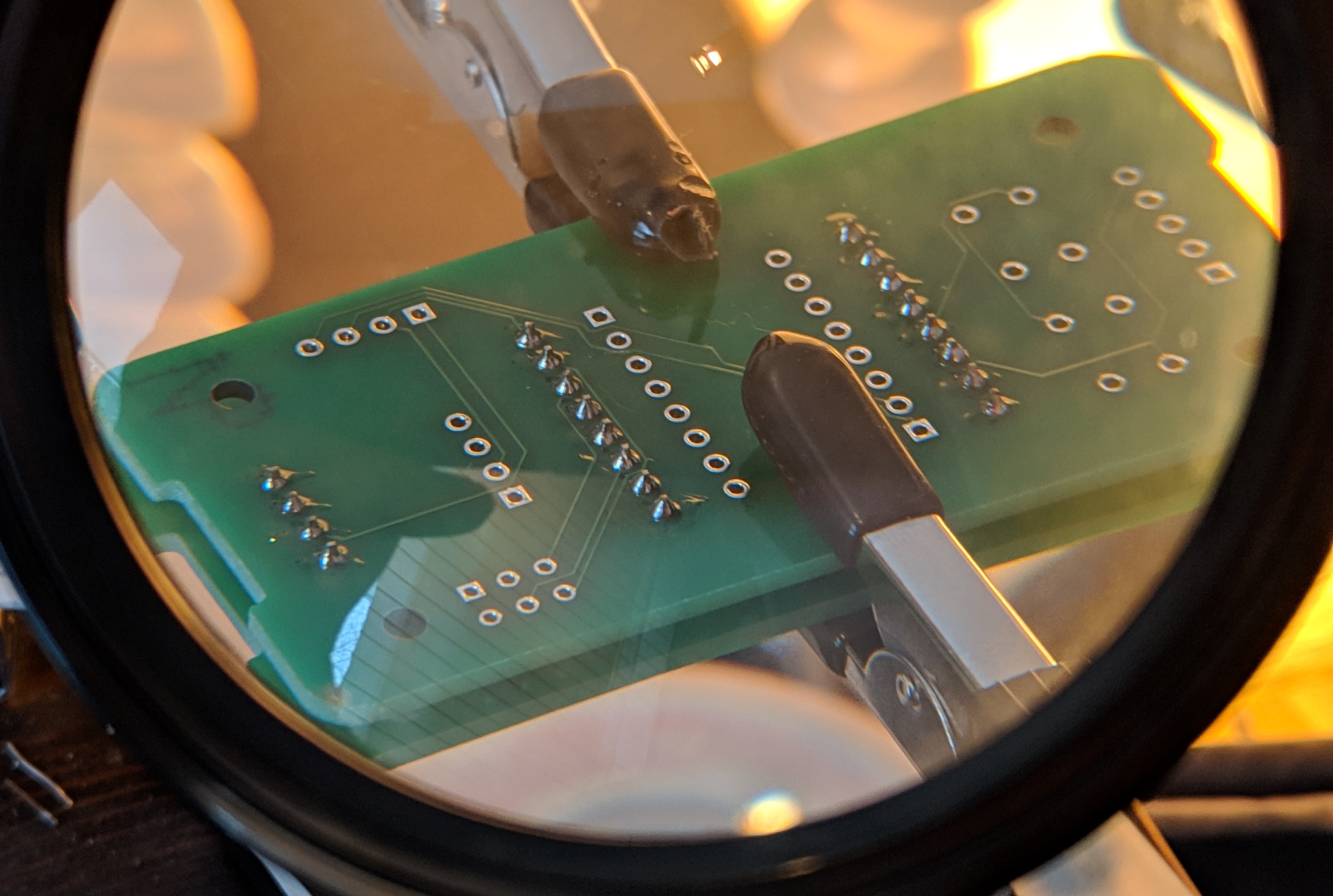
Inspection after soldering
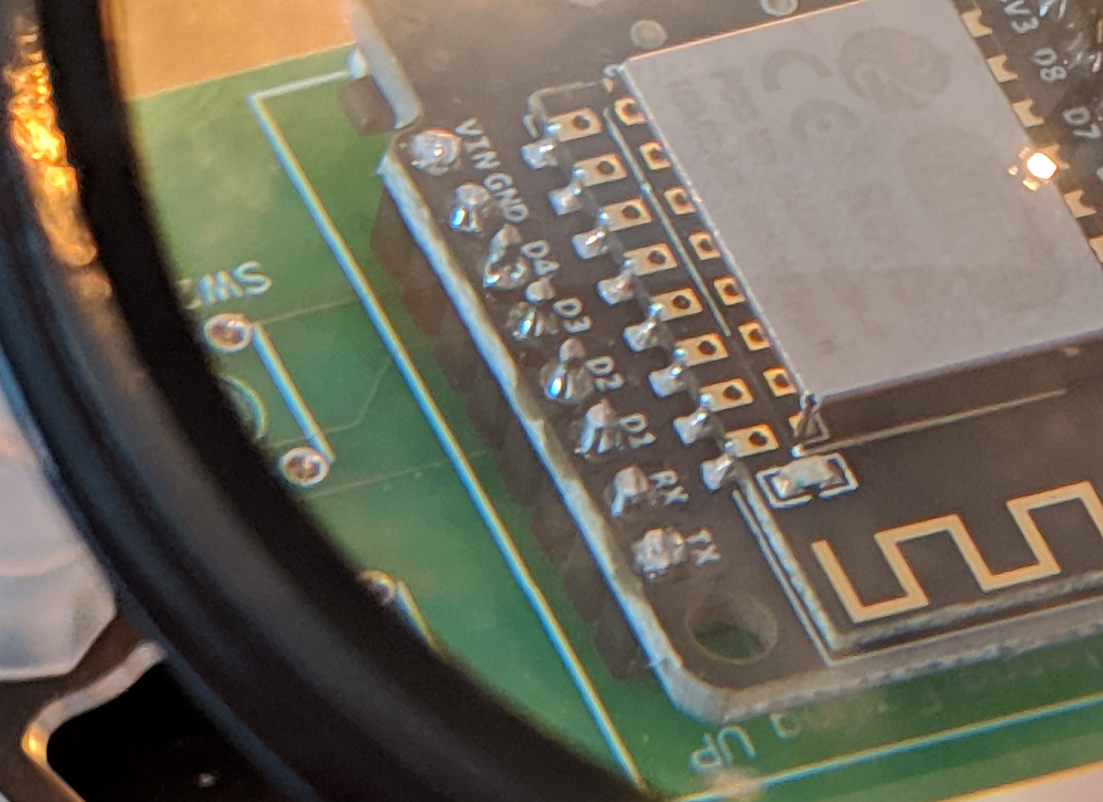
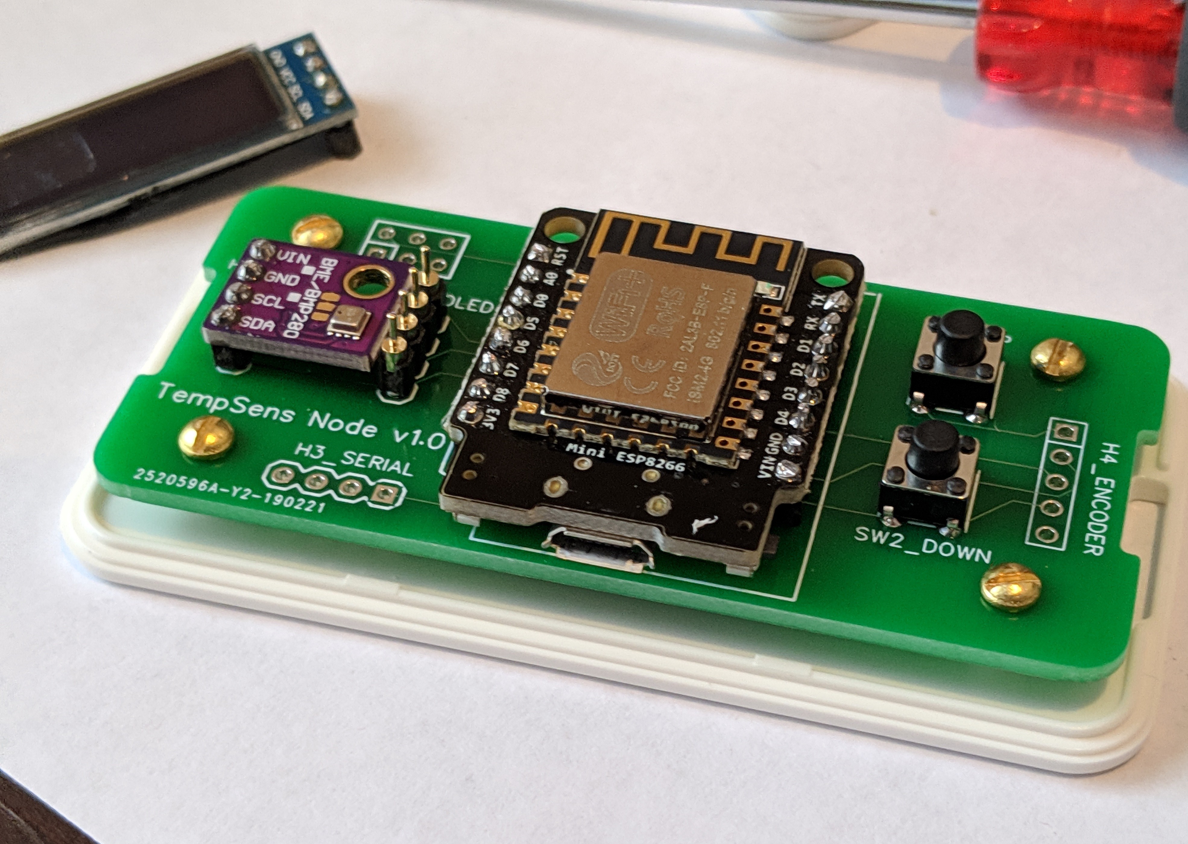
Then the top blank PCB is removed and I put the ESP8266 module in place and solder it down and trim the header leads with flush cutters
Next the BME280 breakout is soldered down
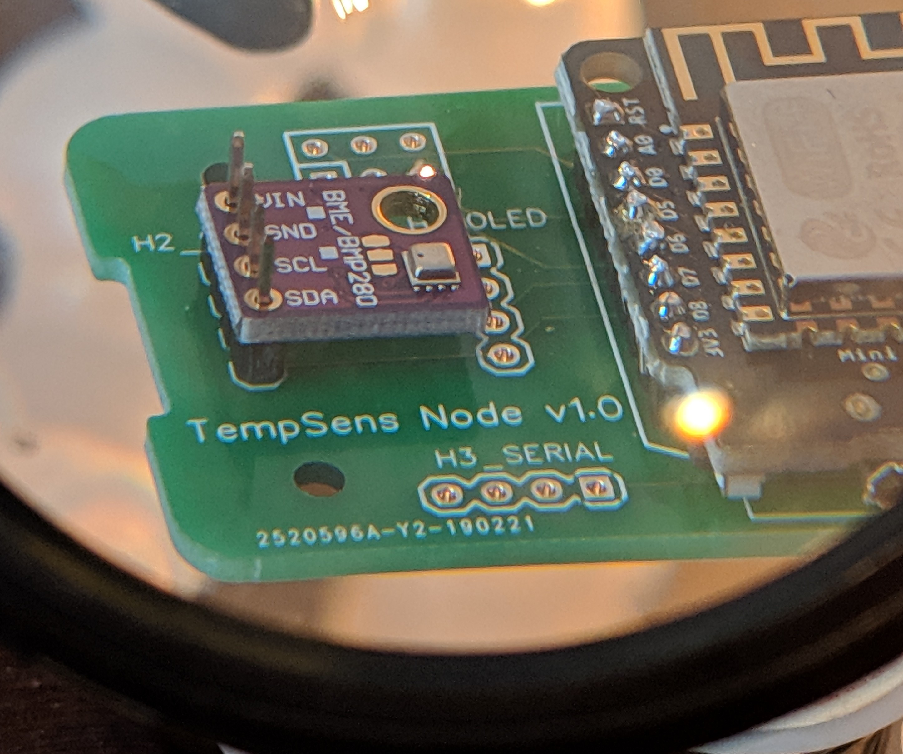
A round milled 1x4 header is soldered in place as a mounting point for the OLED module but this is left as a mating pair not soldered in place.
Two 6x6x6 momentary buttons are soldered down and the completed PCB assembly is screwed down to the Hammond 1551V2WH base plate
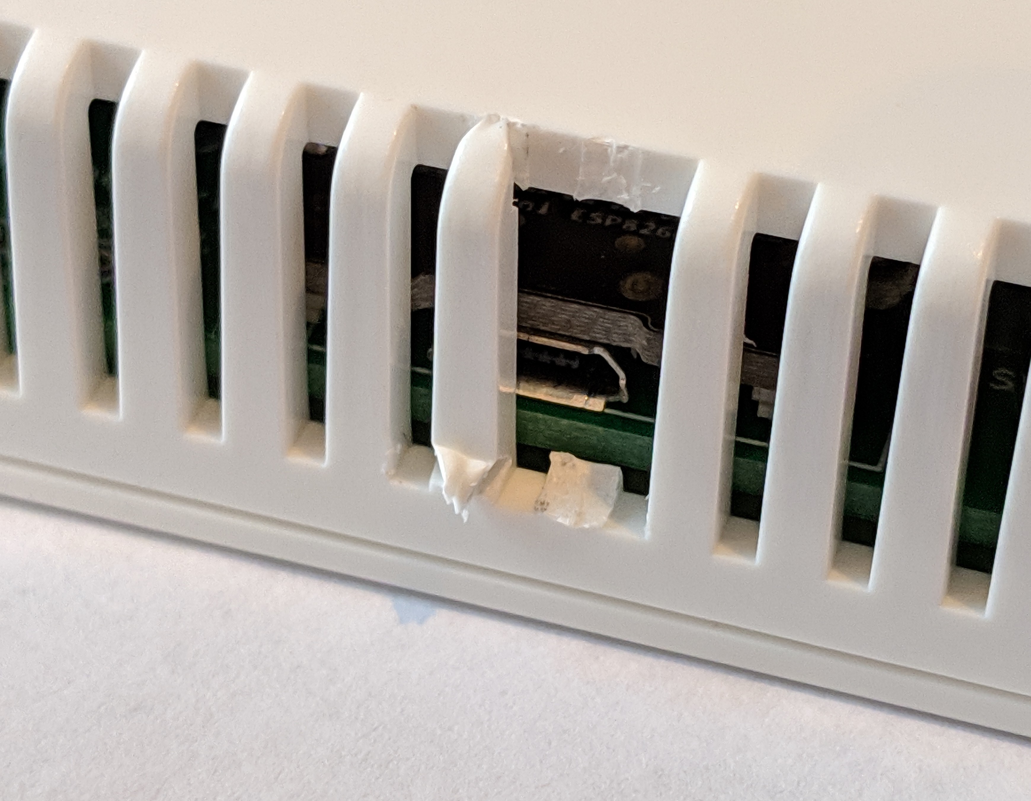
I put the cover on and use flush cutters to cut out two pieces so there is an opening for the micro USB cable end
Discussions
Become a Hackaday.io Member
Create an account to leave a comment. Already have an account? Log In.