 olsen
olsenTo start off there are eight triangle-bit screws around the edge of the device. There is a ninth Phillip's head screw towards the aperture of the projector that secures the laser in place on the inside of the projector. I decided to not mess with it as I might bring it out of alignment and cause all sorts of nasty stuff I don't know how to fix to happen.
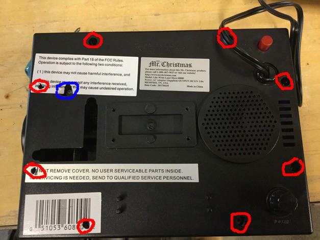
I marked the triangle bits in red, and the Phillip's head in blue. Note the "NO USER SERVICEABLE PARTS INSIDE" sticker. We'll see about that.
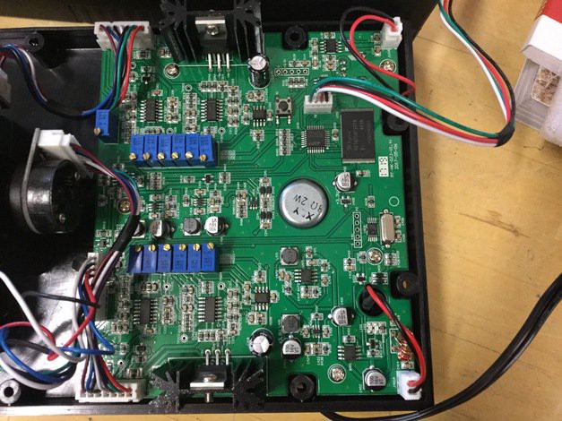
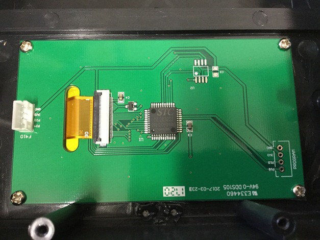
Yay! I'm a little bit intimidated by all those little potentiometers. Most of the board to the left is just two reflections of what appears to be the same circuit. I suspect that this drives the two motors. From previous explorations I've found that the micro is that little one in the top right next to that ROM chip. It's a Silicon Labs C8051F410/2, a Intel 8051 micro compatible with a pair of 12 bit DACs, presumably to drive the motors. Datasheet:
https://www.silabs.com/documents/public/data-sheets/C8051F41x.pdf
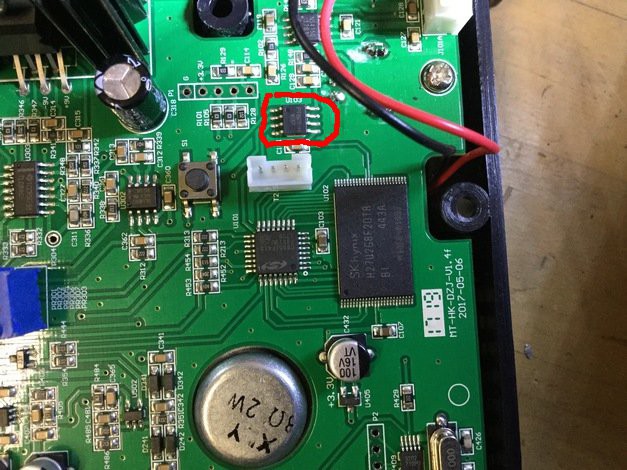
There is a separate 8 pin 16 bit DAC connected to the GPIO of the 8051 for driving the speaker. datasheet:
https://www.futurlec.com/Datasheet/Others/PT8211.pdf
It's circled in the image in red.
I don't know what the button's for, It's not connected to anything. It's strange that they spent money putting it in the BOM if it was only used for testing or something.
Sadly, the EEPROM is too big for my flash jumper, so we won't be able to get a good look at the software and do a software-only hack. What I can do, is place an arduino or similar micro on the top two resistors coming out of the 8051 (Pins 17 and 18 on the datasheet respectively) and drive the motors myself, while leaving all the other stuff intact.
The four-pin cable right next to the 8051 connects to the touchscreen.
Some more closeups of the DAC and an amp.
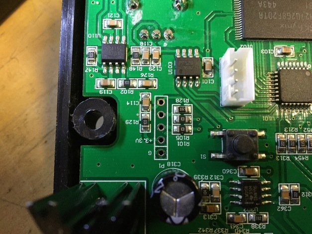
I suspect the 5 pin connector is some sort of debug port. Silicon Labs C2 perhaps?
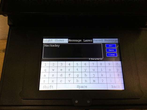
The touchscreen
And here are some photos of it in operation

This has so far been an interesting device to play around with. It's a shame it's so limited.
Let's change that!
Discussions
Become a Hackaday.io Member
Create an account to leave a comment. Already have an account? Log In.