 Ted Yapo
I'm documenting this here so next time I do it, I can just look this up. I needed a decently fast level translator from LVCMOS (3.3V supply) to CMOS logic run from a +/-2.5 V split supply. Running logic from a split supply is not something you see very often, so there aren't commercial translators which will do the job.
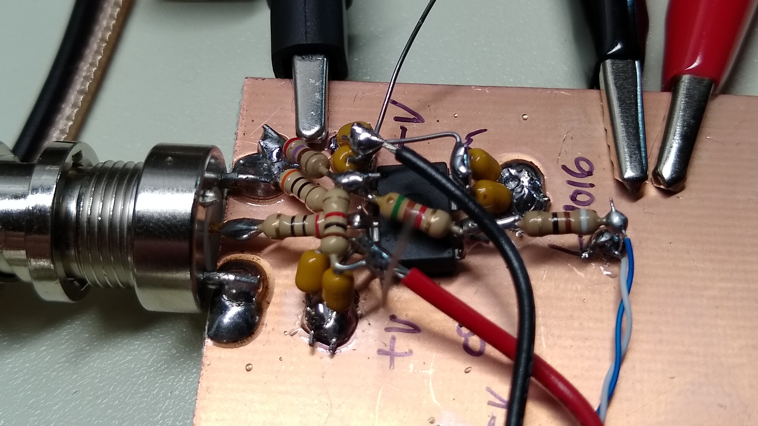
I had a small bag of LT1016 comparators, so I decided to go with that. This comparator was very fast for its day, and it will do for now, although all these years later, there are certainly faster options available. In any case, proper layout is essential with fast comparators, and a healthy dose of positive feedback (hysteresis) keeps things stable.
I didn't want to jam noise back into the input in this case, as you would usually do with a hysteresis arrangement from a non-inverting comparator output. Instead, since the comparator has true and inverted outputs, you can take feedback from the inverting output to the inverting input. This is positive feedback, and makes for some nice hysteresis, which also doesn't depend on the impedance of the input source. In any case, the circuit looks like this:
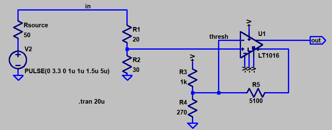
I used wxMaxima to calculate the resistor values. First, the input divider, consisting of R1 and R2. I want this to terminate the input connector in 50 Ohms and also divide the incoming 3.3 V logic signal to a 1 V level. I chose 1 V because the common-mode range of the LT1016 only extends to around 1 V in this circuit (V+ - 1.5 V).
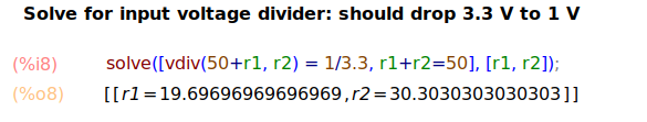
Easy enough. 20 and 30 Ohms are standard 5% values, of which I have a lifetime's supply in 1/4 W through-hole.
Hysteresis Calculations
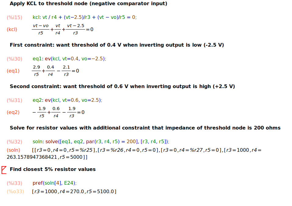
Solving for R3-R5, which determine the hysteresis, is a little more involved. I wanted the thresholds at 0.4 V and 0.6V, for 200 mV of hysteresis. I also wanted the impedance into the inverting input of the comparator to be relatively low, somewhat arbitrarily choosing 200 Ohms.
The approach is to apply Kirchhoff's Current Law (KCL) to the feedback node and create an equation for each of the threshold states. An additional equation sets the impedance of the node to 200 Ohms.
Simulation and Test
Since the LT1016 is a Linear Technology device, it has a model in LTspice. Simulation revealed something I hadn't considered: the outputs are not rail-to-rail. I may have CMOS on the brain. Instead of providing 2.5 V when high, the outputs are closer to 1.2 V.
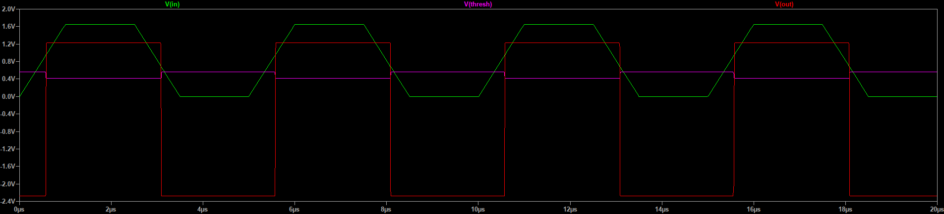
The hysteresis levels in simulation are 420 mV and 558 mV. On the bench, the circuit worked fine with no problems observed. I don't have oscilloscope shots from the bench testing, but they were rather boring anyway.
The circuit seemed to give nice, square outputs up to 20 MHz, then everything kind of started looking linear-ish. I've read that the gain drops off precipitously in these devices around this point, so it's not really surprising. When I get some more time, I'll go back and measure the performance up to 120 MHz or so, which is the limit of my current DDS generator.
If I make this particular circuit again, I might use slightly different resistors to compensate for the lower output values. Using the LTspice simulations shows that the inverting output swings from -2.24 V to +1.22 V. Re-running the maxima calculations gives { R3 = 910, R4 = 270, R5 = 3600 }. Simulation with the new values shows thresholds of 418 mV and 606 mV. These aren't really that different from the ones I originally chose, so maybe it doesn't make much difference.
In any case, I have a decent translator to connect things to logic driven from split supplies now. The output isn't fully rail-to-rail, but the +1.2 V high-level voltage is enough to meet the CMOS high-level input minimum of 1.0 V for the 74LVC gates I'll be driving with it. a more modern comparator might be even better.
Discussions
Become a Hackaday.io Member
Create an account to leave a comment. Already have an account? Log In.