 Laetitia BEL
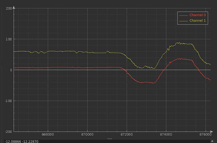
Introduction
In this project, I describe my small odyssey in Ada for embedded ARM to realize from scratch an redundant IMU software and harware environment based on the latest performant IMU, the BMI088. And how to estimate the pitch and roll:
What I want to do, is to be able to control and process a redundant IMU088 (with 13x IMU) to get the best possible result in high vibration environment, an amateur rocket and high precision drones.
For that am using the AdaCore framework and toolchain to benefit from the robust coding environment that they offer highly recognized in safety/reliability oriented industries. Specially for someone who isn't pro in embedded systems using C, not mastering the "savoir faire" of the C can be a headache.
I noticed during the code realization that the Ada code and speclialy the one editied in AdaCore GitHub repo is easily readable.
For someone, like me, who is used to C/C++ and java environment, it wasn't exceptionnaly hard to put the hand on the Ada. Specially that it reminds me Pascal and Caml that I used in very past.
The Super has been developed to be used in amateur rockets for CNRS Planete Science competitions. It will help computing precise attitude in a high vibration environment to stabilize the rocket during the flight using the ailerons.
The SuperIMU has to be embedded in a lancer with a core diameter less than 90mm.
Step 1: System description
The SuperIMU has 13x redundant 6DoF IMU, it can fit in 50mm diameter. It also embeds a compass and barometer which are not redundant.
It will communicate with the microcontroller using the SPI interface to get raw data (accel and gyro data).
We use a simple architecture to visualize and test the SuperIMU:
The SuperIMU sends the raw acceleration/gyroscope rates to the microcontroller using the SPI port.
The microcontroller filter the raw data, and estimate the angles. It sends the angles values using the UART port for analysis purpose.
The UART port is connected to the computer to visualize the data using a serial to USB module.
When tests are satisfying, I will create a specific hosting board for the SuperIMU. The hosting board will be circular using the STM32F746 microcontroller.
The IMU will be distributed as folowing, in a star shape:
The angular distribution follows a 45° pattern:
The previous pattern has been selected to maximize the presence of IMUs over the surface to be able to vary the sensing range.According to a geometrical study conducted in Texas University (Redundant IMU Configurations : paper) where different geometrical configurations:- the geometrical the distribution in a 3D space of the sensor as better results than a distribution on a plan (our case)-- no impact on the accleration (aDOP Accelaration Dilution of Precision)-- impact on the rotation precision (wDOP Angular Dilution of Precision)-- impact on the geometrical precision dillution- the more IMU we add, the more precision we have- the orientation of the IMU doesn't have a significant impact on the result
We keep this study in mind, to reach a cube like configuration we can put two SuperIMU in parallel.For the moment we continue in Unit Circle configuration an try to get the maximum from it.
Sensitivity range configuration: rocket mode
In an amateur rocket the acceleration can reach 8 to 9g during the first seconds of flight.
Here is a typical flight log (acceleration/velocity) of an amateur rocket with the three phases (propulsion, ascending without propulsion, chute opening, diving with chute, earth contact):
During the short flight, the typical acceleration profile is like following:- launching <7 seconds : acceleration >6g- ascending without propulsioin <11s before parachute opening: <3g- diving with parachute <50s : <3g
The sensing range needs to be tolerant to both low and high during the flight to have a precise control. The IMU during will be configured as following:
The sensors raw values will be ignored according to range during the flight:
The filtering process
The acquired data from the IMU (acceleration, angular velocity) are filtered according to their range before starting using it in the angles estimations.
The filtering will offer the complementary filter a reliable
Range Filter:
It get the raw data, and according to the configured range of each IMU, it outputs only the values that are under the threshold : 95% of the configured range.The Range Filter also provides a weight of each measured data according to the configured range. The weight is used to cancel the effect of high range values, it is used by the Average Filter.
The weight has the following values: 0, 1/2, 1/4, 1/8.
For example if the range of the IMU is 3G and the measured acceleration is 2.9G, then the Range Filter outputs the the value coming from this IMU with a zero 0 weight.
For example, if the measured acceleration is <1G, the most accurate IMUs are the ones configured with 3G range. The weight then is 1 from the 3G IMU, the weight from 6G IMU is 1/2, the weight from 12G IMU is 1/4 and the weight from 24G IMU is 1/8.
The weights are computed according to the following table:
Of course, when the measured data is >95% 24G it will be zero weighted.
The output value from the Range Filter is a quadruple (accel, accel_weight, gyro, gyro_weight) for each IMU.
Average Filter:
It computes the average value according to each weight. When the weight is null, the measured values is not taken into account.
The Average Filter outputs the filtered data which is the couple (accel_filtered, gyro_filtered) of the 3-axis.
AHRS Estimator:
The filtered data is then used to estimate the angles.
We will use the well known complementary filter to estimate the flight angles.
TimeSampling
The target st to have a sampling rate of the estimated angles @1ms.That means we need to measure all the 13xIMU, make the filtering and the complementary estimation under the timeframe of 1ms.
To reach this target, we use a STM32F7 board with the possibility to use 6x SPI ports to distribute the data acquisition from the IMUs. But at first we will use only one SPI.
In 1xSPI configuration: the theoryAt 6Mhz SPI (of the STM32F7) one byte takes arround 1.3us on the SPI.To read the accel or gyro (3 axis) it takes 8x1.3us, around 12us.To read both accel and gyro it takes around 25us.To read all the 13xIMUs, it takes around 325us.The remaining 675us are used to filtering and estimation computation.
Experimentally, reading 3-axis accel data takes 35us, and gyro 34us.Which gives 70us per IMU.x13 it takes 910us for all the IMUs.It lets barely 90us for the filtering and estimation.Need to make some optimizations.
Step 2: Hardware Used
BMI088, specially designed for drones and robotics (we will see that -.-).
- It tolerates 24g accelerations.
- The SPI runs at max 10Mhz.
- Resolution: 0.09mg, 0.004 °/s
- low TCO of 0.2 mg/K and low spectral noise of only 230 pg/sqrt(Hz)Maximum
- output data rate: 1.6kHz - each 0.6ms for the accel - max 2000Hz for the gyro - each 0.5ms
Nucleo-F746ZG216MHz runs @200Mhz.
Description of Nucleo-F746ZG:
General characteristics
The most interesting thing with the nucleo boards is that they embed ST Link V2-1 programming interface to allow debuging (ex. with Open OCD or St-Util).
It runs @216Mhz, perferct for my use case that requires fast acquisistion and computation to have the best sampling time.
You need only to connect the board to your computer using a micro usb cable (documentation).For me I use Ubuntu 18.x, the board was automatically detected, no need for any driver installation.
Another interesting thing with the Nucleo boards is that they keep the compatibility with Arduino Uno header.Represented in green (D0...D13) below.
Source: https://os.mbed.com/platforms/ST-Nucleo-F746ZG/
Since we need to reduce the latency to maximum while reading from the BMI088 sensors (13x IMU) we use the SPI port to get the Accel and Gyro data.
For the code we will use the SPI1 of the STM32F746 :
- SCK : PA_5
- MISO: PA_6
- MOSI: PA_7
Description of the Super IMU:
The SuperIMU is based on the BMI088, it uses the SPI interface to configure et get the data of the IMU. From the datasheet the user circuit is the following:
In the case of the SuperIMU there is no use of interrupts, it gets the data in sequence. The SDO of the ACCEL and GYRO gos to the same output in the board.
I have to select each Gyro and Accel indivudially.
Schematics for AdaIMU BMI088 Circle (SuperIMU)
The SuperIMU is designed with the possibility to acquire the data using a single SPI (next version will be with multiple SPIs), it has 13x BMI088 :
Here is how it looks like. I need to solder the headers to connect the DuPont wires:
In the back there are the description of the pins, there the SPI (SDO/SCK/SDI) and the pins to select the gyros and the acccels:
Here is how it looks like after finishing the soldering:
La pieuvre:
The SuperIMU is connected to the Nucleo Board using the 3v3 supply and SPI port 1.
The GPIO pins are used to select the Gyro and Accel of the 13x IMUs will be done as following:
The definition of the GPIO pins to select the Gyros/Accelerometers of the IMUs:
-- IMU select type IMU_Select_Point is record AccelPoint : GPIO_Point; GyroPoint : GPIO_Point; end record; IMU1_SPI1_SELC : GPIO_Point renames PC8; IMU1_SPI1_SELG : GPIO_Point renames PC9; IMU2_SPI1_SELC : GPIO_Point renames PC10; IMU2_SPI1_SELG : GPIO_Point renames PC11; IMU3_SPI1_SELC : GPIO_Point renames PC12; IMU3_SPI1_SELG : GPIO_Point renames PD2; IMU4_SPI1_SELC : GPIO_Point renames PG2; IMU4_SPI1_SELG : GPIO_Point renames PG3; IMU5_SPI1_SELC : GPIO_Point renames PD7; IMU5_SPI1_SELG : GPIO_Point renames PD6; IMU6_SPI1_SELC : GPIO_Point renames PD5; IMU6_SPI1_SELG : GPIO_Point renames PD4; IMU7_SPI1_SELC : GPIO_Point renames PD3; IMU7_SPI1_SELG : GPIO_Point renames PE2; IMU8_SPI1_SELC : GPIO_Point renames PE4; IMU8_SPI1_SELG : GPIO_Point renames PE5; IMU9_SPI1_SELC : GPIO_Point renames PE6; IMU9_SPI1_SELG : GPIO_Point renames PE3; IMU10_SPI1_SELC : GPIO_Point renames PF8; IMU10_SPI1_SELG : GPIO_Point renames PF7; IMU11_SPI1_SELC : GPIO_Point renames PF9; IMU11_SPI1_SELG : GPIO_Point renames PG1; IMU12_SPI1_SELC : GPIO_Point renames PA3; IMU12_SPI1_SELG : GPIO_Point renames PC0; IMU13_SPI1_SELC : GPIO_Point renames PC3; IMU13_SPI1_SELG : GPIO_Point renames PF3; IMU_SPI1_SEL_Points : constant STM32.GPIO.GPIO_Points := (IMU1_SPI1_SELC, IMU1_SPI1_SELG, IMU2_SPI1_SELC, IMU2_SPI1_SELG, IMU3_SPI1_SELC, IMU3_SPI1_SELG, IMU4_SPI1_SELC, IMU4_SPI1_SELG, IMU5_SPI1_SELC, IMU5_SPI1_SELG, IMU6_SPI1_SELC, IMU6_SPI1_SELG, IMU7_SPI1_SELC, IMU7_SPI1_SELG, IMU8_SPI1_SELC, IMU8_SPI1_SELG, IMU9_SPI1_SELC, IMU9_SPI1_SELG, IMU10_SPI1_SELC, IMU10_SPI1_SELG, IMU11_SPI1_SELC, IMU11_SPI1_SELG, IMU12_SPI1_SELC, IMU12_SPI1_SELG, IMU13_SPI1_SELC, IMU13_SPI1_SELG); IMU_SPI1_Accel_SEL_Points : array (1 .. 13) of access GPIO_Point'Class := ( IMU1_SPI1_SELC'Access, IMU2_SPI1_SELC'Access, IMU3_SPI1_SELC'Access, IMU4_SPI1_SELC'Access, IMU5_SPI1_SELC'Access, IMU6_SPI1_SELC'Access, IMU7_SPI1_SELC'Access, IMU8_SPI1_SELC'Access, IMU9_SPI1_SELC'Access, IMU10_SPI1_SELC'Access, IMU11_SPI1_SELC'Access, IMU12_SPI1_SELC'Access, IMU13_SPI1_SELC'Access ); IMU_SPI1_Gyro_SEL_Points : array (1 .. 13) of access GPIO_Point'Class := ( IMU1_SPI1_SELG'Access, IMU2_SPI1_SELG'Access, IMU3_SPI1_SELG'Access, IMU4_SPI1_SELG'Access, IMU5_SPI1_SELG'Access, IMU6_SPI1_SELG'Access, IMU7_SPI1_SELG'Access, IMU8_SPI1_SELG'Access, IMU9_SPI1_SELG'Access, IMU10_SPI1_SELG'Access, IMU11_SPI1_SELG'Access, IMU12_SPI1_SELG'Access, IMU13_SPI1_SELG'Access );
Step 3: Filtering and Estimation Description
Filtering Code:
Estimation Code:
I used a simple complementary filter to estimate the pitch and the roll. We get the acceleration and gyro rate data from the IMUs.
The code is here after:
procedure ComplementaryFilter(accelData : Sensor_Accel_Data; gyroData : Sensor_Gyro_Data) is pitchAccel : Float := 0.0; -- pitch computed from the accel rollAccel : Float := 0.0; -- roll computed from the accel begin -- integrate the gyroscope data estimatedPitch := estimatedPitch + gyroData(X)*dt; estimatedRoll := estimatedRoll + gyroData(Y)*dt; -- compensate the drift using the acceleration pitchAccel := Ada.Numerics.Elementary_Functions.Arctan(accelData(Y),accelData(Z))*RadToDeg; estimatedPitch := estimatedPitch * 0.98 + pitchAccel * 0.02; rollAccel := Ada.Numerics.Elementary_Functions.Arctan(accelData(X),accelData(Z))*RadToDeg; estimatedRoll := estimatedRoll * 0.98 + rollAccel * 0.02; null; end ComplementaryFilter;
Step 4 : Software Setup / IDE
Using Adacore GPS IDE
I installed the GPS IDE from Adacore website: gnat-community-2018-20180528-x86_64-linux-bin, it has a cool editor with included debuging interface and all the check environment for Ada and SPARK.
I installed the Arm-ELF compilers from Adacore website: gnat-community-2018-20180524-arm-elf-linux64-bin, it provides the compilers and builders toolchain for ARM.
Using Ada_Drivers_Library
To be able to compile the code for the drivers, I got the libraries and the board from GitHub repository of AdaCore: https://github.com/AdaCore/Ada_Drivers_Library
It contains a lot of the drivers, svd, examples and boards for different micro-controllers.
Since we use STM32F746 microcontroller, I stared from the existing code for the STM32F7654_Disco board.
I used the existing example STM32F7654_Disco.
What I did is just copy past existing STM32F7654_Disco into STM32F7654_Nucleo for the board and example to make the modifications.
To update the code from from disco to nucleo is easy, alsmost nothing to do except updating some paths in the example gpr file.
Step 5: A Blink Test Before All!
Before continuing I need to make sure that the board can be programmed correctly.I went for a blink hello word.
I kept the existing file: blinky_f7disco.gpr, with the following modification of the path. No problem to keep using stm32f746_discovery_full.gpr
with "../../boards/stm32f746_nucleo/stm32f746_discovery_full.gpr";
The blinky_f7disco uses the following main entry:
Ada_Drivers_Library/examples/shared/hello_world_blinky/src/blinky.adb
The content of blinky looks like:
with STM32.Board;   use STM32.Board;
with STM32.GPIO;    use STM32.GPIO;
with Ada.Real_Time; use Ada.Real_Time;
procedure Blinky is  Period : constant Time_Span := Milliseconds (200);  -- arbitrary  Next_Release : Time := Clock;
begin  STM32.Board.Initialize_LEDs;  loop     Toggle (All_LEDs);     Next_Release := Next_Release + Period;     delay until Next_Release;  end loop;
end Blinky;
It seems that this code is common to all the boards.Using GPS IDE I followed the definition of All_LEDs, it is defined in:
Ada_Drivers_Library/boards/stm32_common/stm32f746disco/stm32-board.ads
The value All_LEDs is a set with index 1 is pointing to PI1:
Green_LED : User_LED renames PI1; LED1 : User_LED renames Green_LED; LCH_LED : User_LED renames Green_LED; All_LEDs : GPIO_Points := (1 => Green_LED);
In the Nucleo board there is no LED linked to PI1, to find out what output I can use, the easy way is to check the schematics of nucleo https://www.st.com/resource/en/schematic_pack/nucleo_144pins_sch.zip
I took the blue LED conected to PB7. The code then updated to blue:
Blue_LED : User_LED renames PB7; LED1 : User_LED renames Blue_LED; LCH_LED : User_LED renames Blue_LED; All_LEDs : GPIO_Points := (1 => Blue_LED);
The code is then uploaded using the upload button (important you need to configure your upload/debug too, in my case I use OpenOCD as described below)
The code compiles well, correctly uploaded and bam the blue LED blinks:
Let's then start the serious work. Making a SPI driver for the BMI088.
Step 6: Making Driver for BMI088
The cool thing is that Ada_Drivers_Library has alreay some examples of SPI IMU in "components/src/motion" directory.
I just got to use the l3gd20 to start the driver for the bmi088 for inspiration.
To chose correctly the registers and the protocol characteristics here are the used resources:- BST-BMI088-DS001- officiel C drivers: usefull to gain time
For information a demo of the existing driver is located in the path: Ada_Drivers_Library/arch/ARM/STM32/driver_demos/
Updating the board definition : define SPI1In file stm32-board.ads in the STM32.Board package body we add:
--------------------------------- -- SPI1 / IMU BMI088 example -- --------------------------------- -- SPI Port IMU_SPI : SPI_Port renames SPI_1; -- SPI IOs SPI1_SCK : GPIO_Point renames PA5; -- D13 in connector CN10 SPI1_MISO : GPIO_Point renames PA6; -- D14 in connector CN10 SPI1_MOSI : GPIO_Point renames PA7; -- D15 in connector CN10 -- IMU select IMU_SEL1 : GPIO_Point renames PG9; -- D0 in connector CN10 -- To initialize the SPI1 port for the BMI088 procedure Initialize_SPI1_For_BMI088;
The trick to use the SPI in 8bits in STM32F7
It is important for the BIM088 to communicate with 8bits.However the data tx/rx DR register is 16bits, by default it sends 16bits.A first write/read : NOK
The trick is, according to the reference manual is to configure the register DS (data size) to 4bits and format correctly the data written in the DR register.
That's why I updated the default driver of the SPI (stm32-spi.adb) as following of the write/read 8 bits mode.
procedure Configure (This : in out SPI_Port; Conf : SPI_Configuration) is  begin
...    This.Periph.CR1.DFF     := Conf.Data_Size = HAL.SPI.Data_Size_16b;     This.Periph.CR2.DS      := STM32_SVD.SPI.Size_4Bit; -- add this line     This.Periph.CR1.CPOL     := Conf.Clock_Polarity = High;
...
procedure Send_8bit_Mode    (This     : in out SPI_Port;     Outgoing : HAL.SPI.SPI_Data_8b)  is     Tx_Count : Natural := Outgoing'Length;     Index    : Natural := Outgoing'First;     Tmp : UInt16;  begin     if Current_Mode (This) = Slave or else Tx_Count = 1 then        Tmp := UInt16 ((Outgoing (Index) and 16#0F#))*256 + UInt16((Outgoing (Index) and 16#F0#))/16;        This.Periph.DR.DR := Tmp;        Index := Index + 1;        Tx_Count := Tx_Count - 1;     end if;
...
procedure Receive_8bit_Mode    (This     : in out SPI_Port;     Incoming : out HAL.SPI.SPI_Data_8b)  is     Generate_Clock : constant Boolean := Current_Mode (This) = Master;     Tmp : Uint16;  begin     for K of Incoming loop        if Generate_Clock then           This.Periph.DR.DR := 0;        end if;        while Rx_Is_Empty (This) loop           null;        end loop;        Tmp := This.Periph.DR.DR;        K := UInt8 (Tmp and 16#000F#)*16+ UInt8 ((Tmp and 16#0F00#)/256);
...
This way I got better clocking, and the read/write in the BMI088's register work fine in 8 bits mode:
But still not OK:
Because we need to always discard the first received byte from the BMI088 when reading the accelerometer (not the case of the gyro). This why each time that I make a read, I have to read the dummy byte before.With this update I had better results.
In the BMI088.adb:
---------- -- Read -- ---------- procedure Accel_Read (This : Six_Axis_Imu; Addr : Register; Data : out UInt8) is Status : SPI_Status; Tmp_Data : SPI_Data_8b (1 .. 1); begin SPI_Mode (This, Enabled => True); -- select the chip This.Port.Transmit (SPI_Data_8b'(1 => UInt8 (Addr) or ReadWrite_CMD), Status); if Status /= Ok then raise Program_Error; end if; This.Port.Receive (Tmp_Data, Status); -- dummy constraint BMI088 This.Port.Receive (Tmp_Data, Status); if Status /= Ok then raise Program_Error; end if; Data := Tmp_Data (Tmp_Data'First); SPI_Mode (This, Enabled => False); -- unselect the chip end Read; ---------------- -- Read_UInt8s -- ---------------- procedure Accel_Read_UInt8s (This : Six_Axis_Imu; Addr : Register; Buffer : out SPI_Data_8b; Count : Natural) is Index : Natural := Buffer'First; Status : SPI_Status; Tmp_Data : SPI_Data_8b (1 .. 1); begin SPI_Mode (This, Enabled => True); This.Port.Transmit (SPI_Data_8b'(1 => UInt8 (Addr) or ReadWrite_CMD), Status); if Status /= Ok then raise Program_Error; end if; This.Port.Receive (Tmp_Data, Status); -- dummy constraint BMI088 for K in 1 .. Count loop This.Port.Receive (Tmp_Data, Status); if Status /= Ok then raise Program_Error; end if; Buffer (Index) := Tmp_Data (Tmp_Data'First); Index := Index + 1; end loop; SPI_Mode (This, Enabled => False); end Read_UInt8s;
This is better to read the accel data from the register. In the following image, we represent only SDO and the clock (SDI not represented, I have only 2 probes... :'( ) :
For the gyroscope data there no issue with dummy byte.
This is why it is necessary to have Accel_Read and Gyro_Read different procedures.
The steps to initialize the BMI088
First you you need to initialize the SPI correctly to communicate with the BMI088 by calling the following procedure:
procedure Initialize_SPI1_For_BMI088 is Config : GPIO_Port_Configuration; Config_SPI : SPI_Configuration; begin -- Enable the clocks Enable_Clock (IMU_SPI); Enable_Clock (SPI1_Points); Enable_Clock (IMU_SEL1); -- Configure the SPI IOs Config := (Mode => Mode_AF, AF => GPIO_AF_SPI1_5, AF_Speed => Speed_100MHz, AF_Output_Type => Push_Pull, Resistors => Floating); Configure_IO(SPI1_Points, Config); -- Configure the SPI select chip IOs Config := (Mode => Mode_Out, Speed => Speed_25MHz, Output_Type => Push_Pull, Resistors => Pull_Up); Configure_IO(IMU_SEL_Points, Config); -- Configure the SPI1 port Config_SPI := (Direction => D2Lines_FullDuplex, Mode => Master, Data_Size => HAL.SPI.Data_Size_8b, Clock_Polarity => Low, Clock_Phase => P1Edge, Slave_Management => Software_Managed, Baud_Rate_Prescaler => BRP_32 First_Bit => MSB, CRC_Poly => 7); Configure (IMU_SPI, Config_SPI); STM32.SPI.Enable (IMU_SPI); end Initialize_SPI1_For_BMI088;
Then follow the steps below for the accelerometer (the values of the registers and commands are defined in the datasheet, you can find them in the final driver at the end):
---- check the device ID  Bmi.Read(ACC_CHIP_ID_ADDR, Result);  while Result /= ACC_CHIP_ID loop     Bmi.Read(ACC_CHIP_ID_ADDR, Result);     delay until Clock + Milliseconds (1);  end loop;
---- reset the accel  Bmi.Write(ACC_SOFT_RESET_ADDR,ACC_RESET_CMD);  delay until Clock + Milliseconds (50);  Turn_ON(IMU_SEL1);  delay until Clock + Milliseconds (5);  Turn_Off(IMU_SEL1);  delay until Clock + Milliseconds (5);
---- enable the accel (rundandant to make sure it works)  Bmi.Write(ACC_PWR_CNTRL_ADDR,ACC_ENABLE_CMD);  delay until Clock + Milliseconds (50);    Bmi.Read(ACC_PWR_CNTRL_ADDR, Result);  while Result /= ACC_ENABLE_CMD loop     Bmi.Write(ACC_SOFT_RESET_ADDR,ACC_RESET_CMD);     --delay until Clock + Milliseconds (1);     Bmi.Write(ACC_PWR_CNTRL_ADDR,ACC_ENABLE_CMD);     --delay until Clock + Milliseconds (50);     Bmi.Read(ACC_PWR_CNTRL_ADDR, Result);     delay until Clock + Microseconds (4);  end loop;
---- enter active mode  Bmi.Write(ACC_PWR_CONF_ADDR,ACC_ACTIVE_MODE_CMD);  delay until Clock + Milliseconds (5);  Bmi.Read(ACC_PWR_CONF_ADDR, Result);  while Result /= ACC_ACTIVE_MODE_CMD loop     Bmi.Write(ACC_PWR_CONF_ADDR,ACC_ACTIVE_MODE_CMD);     delay until Clock + Milliseconds (5);     Bmi.Read(ACC_PWR_CONF_ADDR, Result);  end loop;
---- set range 24G  Bmi.Write(ACC_RANGE_ADDR,RANGE_24G);  delay until Clock + Milliseconds (1);  Bmi.Read(ACC_RANGE_ADDR, Result);  while Result /= RANGE_24G loop     Bmi.Read(ACC_RANGE_ADDR, Result);  end loop;
---- set default ODR  Bmi.Write(ACC_ODR_ADDR,ODR_1600HZ_BW_280HZ);  delay until Clock + Milliseconds (1);  Bmi.Read(ACC_ODR_ADDR, Result);  while Result /= ODR_1600HZ_BW_280HZ loop     Bmi.Read(ACC_ODR_ADDR, Result);  end loop;
---- check if there is an error  Bmi.Read(ACC_ERR_CODE_ADDR, Result);  while Result /= 16#0# loop     Bmi.Read(ACC_ERR_CODE_ADDR, Result);  end loop;  ---- read the value  loop     Bmi.Read_UInt8s(ACC_ACCEL_DATA_ADDR,Received,6);     delay until Clock + Microseconds (100);  end loop;
By following the above steps I got the values using SPI from the BMI088.
Step 7: Debuging
with OpenOCD
You can also use st-util, in my case I aleady did the work for openocd, that's why am using it.
Important (a 3 hours gain time comment): you need to run gnat gps in sudo mode, else openocd can't have access to the usb port
Installing OpenOCDThe best way to use the OpenOCD on ubuntu is by building. This way you have the last version.I used the OpenOCD from gnu-mcu-eclipse/openocd.
To build it:
you need to install libusb dev v1.0 then
# ./configure --enable-stlink # make # sudo make install
The configuration used for the OpenOCD:- the port is 3333 for local host- I used the configuration file of stm32f74discovery from openocd github.
Debuging SPI Using CYUSB3KIT-003 with Analyzer2go
The Analyzer2Go is just an amazing tool for small budgets. Combined to the board CYUSB3KIT-003 (45$) you have a powerful 16x channels analyzer at 200MHz sampling rate!
For my case, the exchange with the SPI/UART are under the 10Mhz, and reading the MCO of the Nucleo board (PLL under the 100MHz), it is sufficient.
SPI Tests
For the first driver tests I used the TINKER IMU BMI088 similar to SeeedStudio Grove 6-Axis Accelerometer & Gyroscope (BMI088)The problem with the IMU from SeedStudio is that it supports only I2C.
The TINKER IMU BMI088 breakout supports both SPI and I2C.
The speed of the SPI is configured to 6MHz (baud rate DIV 32) of the STM32F746.
I can get the IMU motion data correctly using the SPI using from a BMI088 instance, using the procedure:
procedure ReadAccelRates (This : in out Six_Axis_Imu; Result : out Sensor_Accel_Data); procedure ReadGyroRates (This : in out Six_Axis_Imu; Result : out Sensor_Gyro_Data);
Step 9: Estimations Tests
The test setup:
- IMU BMI088 connected using SPI to the microcontroller. One IMU is used, waiting finishing the super IMU.
- USB To UART to send roll and pitch
- The nucleo board
The result has something like that: https://i.imgur.com/ddpCtUG.mp4
Step 10: PLL Clocking tests:
In the nucleo board the external high speed clock (HSE) doesn't come from the crystal 25MHz, but comes from the ST-Link chip @8MHz.After hours of debuging, I had finaly to modify the adl_config.ads and the s-bbbopa.ads (as workarround) file to set the right value of the HSE clock.I had finally to create a new BSP for Nucleo-F746 rather than using the stm32f746disco because of this difference.
Now that the clock is correctly operational, the measurement show time:
Reading an accel value takes 35us in debug mode.
I used the flowing code to toggle the pin PG1 upon the end of reading values from IMU:
-------------------- -- ReadAccelRates -- -------------------- procedure ReadAccelRates (This : in out Six_Axis_Imu; Result : out Sensor_Data) is Received : SPI_Data_8b (1 .. 6); -- 2 bytes per axis AccelRates : BMI088.IMU_Rates;-- todo create AccelRate type begin PG1.Set; This.AccelRead_UInt8s(ACC_ACCEL_DATA_ADDR,Received,6); AccelRates.X := As_IMU_Rates_Pointer (Received (1)'Address).all; AccelRates.Y := As_IMU_Rates_Pointer (Received (3)'Address).all; AccelRates.Z := As_IMU_Rates_Pointer (Received (5)'Address).all; Result(X) := Float (AccelRates.X) / 32768.0 * Accel_Range_MSS; Result(Y) := Float (AccelRates.Y) / 32768.0 * Accel_Range_MSS; Result(Z) := Float (AccelRates.Z) / 32768.0 * Accel_Range_MSS; PG1.Clear; end ReadAccelRates;
Reading a full Gyro values takes 34us in debug mode.
   -------------------  -- ReadGyroRates --  -------------------  procedure ReadGyroRates (This : in out Six_Axis_Imu;                            Result   : out Sensor_Data)  is     Received        : SPI_Data_8b (1 .. 6); -- 2 bytes per axis     GyroRates : BMI088.IMU_Rates;-- todo create AccelRate type  begin
PG1.Set;     This.AccelRead_UInt8s(ACC_ACCEL_DATA_ADDR,Received,6);     GyroRates.X := As_IMU_Rates_Pointer (Received (1)'Address).all;     GyroRates.Y := As_IMU_Rates_Pointer (Received (3)'Address).all;     GyroRates.Z := As_IMU_Rates_Pointer (Received (5)'Address).all;     Result(X) := Float (GyroRates.X) / 32768.0 * Gyro_Range_Rads;     Result(Y) := Float (GyroRates.Y) / 32768.0 * Gyro_Range_Rads;     Result(Z) := Float (GyroRates.Z) / 32768.0 * Gyro_Range_Rads;
PG1.Clear;  end ReadGyroRates;
Step 11: Using UART to Plot Data
To visualize the output data, I'd like to use UART to be able to visualize it in the super amazing cool serial plotter : https://github.com/CieNTi/serial_port_plotter
The problem now is to convert Float to String.. to send it using UART to the Serial_Port_Plotter tool.
To do that I used the magical word 'Img in Ada as suggested here to convert Float to String. Then send the string byte by byte to the UART.
If you want to send one value: - send "$" - send float value - send ";"
If you want to send multiple values: - send "$" to start - send float value 1 - send space " " ... - send float value i - send space " " - send ";" to terminate
To be able to send an acceleration to the plotter, I used the following code:
     type FixedFloat is delta 0.00001 digits 18;
---     data_1B(0) := UInt8(36); -- '$'     UART_OUT.Transmit(data_1B,status);     for ch of FixedFloat(AccelRates(X))'Img loop        c := Character(ch);        data_1B(0) := Character'Pos(c);        UART_OUT.Transmit(data_1B,status);     end loop;     data_1B(0) := UInt8(59); -- ';'     UART_OUT.Transmit(data_1B,status);
The result is very satisfying, in the snapshot bellow I visualize the Accelerometer(X) value in real time:
After creating the driver, that data is correctly sent through UART port:
Making driver for UART
Unfortunately in the STM32F7 device there is no UART driver yet (just for STM32F4).
To create a driver for UART I started from the stm32-usarts.ads/adb for the STM32F4.I modified the files to be compliant with the SVD of the STM32F7. I had also to modify the STM32-Device.ads/adb to include properly the UART/USART definitions of the STM32F7.
It works fine for transmitting bytes of 9 or 8bits size. I didn't test it for DMA style (because never did it :) )
Code ads:
------------------------------------------------------------------------------
--                                                                          --
--                  Copyright (C) 2015-2016, AdaCore                        --
--                                                                          --
--  Redistribution and use in source and binary forms, with or without      --
--  modification, are permitted provided that the following conditions are  --
--  met:                                                                    --
--     1. Redistributions of source code must retain the above copyright    --
--        notice, this list of conditions and the following disclaimer.     --
--     2. Redistributions in binary form must reproduce the above copyright --
--        notice, this list of conditions and the following disclaimer in   --
--        the documentation and/or other materials provided with the        --
--        distribution.                                                     --
--     3. Neither the name of STMicroelectronics nor the names of its       --
--        contributors may be used to endorse or promote products derived   --
--        from this software without specific prior written permission.     --
--                                                                          --
--   THIS SOFTWARE IS PROVIDED BY THE COPYRIGHT HOLDERS AND CONTRIBUTORS    --
--   "AS IS" AND ANY EXPRESS OR IMPLIED WARRANTIES, INCLUDING, BUT NOT      --
--   LIMITED TO, THE IMPLIED WARRANTIES OF MERCHANTABILITY AND FITNESS FOR  --
--   A PARTICULAR PURPOSE ARE DISCLAIMED. IN NO EVENT SHALL THE COPYRIGHT   --
--   HOLDER OR CONTRIBUTORS BE LIABLE FOR ANY DIRECT, INDIRECT, INCIDENTAL, --
--   SPECIAL, EXEMPLARY, OR CONSEQUENTIAL DAMAGES (INCLUDING, BUT NOT       --
--   LIMITED TO, PROCUREMENT OF SUBSTITUTE GOODS OR SERVICES; LOSS OF USE,  --
--   DATA, OR PROFITS; OR BUSINESS INTERRUPTION) HOWEVER CAUSED AND ON ANY  --
--   THEORY OF LIABILITY, WHETHER IN CONTRACT, STRICT LIABILITY, OR TORT    --
--   (INCLUDING NEGLIGENCE OR OTHERWISE) ARISING IN ANY WAY OUT OF THE USE  --
--   OF THIS SOFTWARE, EVEN IF ADVISED OF THE POSSIBILITY OF SUCH DAMAGE.   --
--                                                                          --
--                                                                          --
--  This file is based on:                                                  --
--                                                                          --
--   @file    stm32f4xx_hal_usart.h                                         --
--   @author  MCD Application Team                                          --
--   @version V1.1.0                                                        --
--   @date    19-June-2014                                                  --
--   @brief   Header file of USARTS HAL module.                             --
--                                                                          --
--   COPYRIGHT(c) 2014 STMicroelectronics                                   --
------------------------------------------------------------------------------
--  This file provides register definitions for the STM32F4 (ARM Cortex M4F)
--  USART from ST Microelectronics.
--  Note that there are board implementation assumptions represented by the
--  private function APB_Clock.
with System;
with HAL.UART; use HAL.UART;
private with STM32_SVD.USART;
package STM32.USARTs is  type Internal_USART is limited private;  type USART (Periph : not null access Internal_USART) is    limited new HAL.UART.UART_Port with private;  procedure Enable (This : in out USART) with    Post => Enabled (This),    Inline;  procedure Disable (This : in out USART) with    Post => not Enabled (This),    Inline;  function Enabled (This : USART) return Boolean with Inline;  procedure Receive (This : USART;  Data : out UInt9) with Inline;  --  reads Device.DR into Data  function Current_Input (This : USART) return UInt9 with Inline;  --  returns Device.DR  procedure Transmit (This : in out USART;  Data : UInt9) with Inline;  function Tx_Ready (This : USART) return Boolean with Inline;  function Rx_Ready (This : USART) return Boolean with Inline;  type Stop_Bits is (Stopbits_1, Stopbits_2) with Size => 2;  for Stop_Bits use (Stopbits_1 => 0, Stopbits_2 => 2#10#);  procedure Set_Stop_Bits (This : in out USART;  To : Stop_Bits);  type Word_Lengths is (Word_Length_8, Word_Length_9);  procedure Set_Word_Length (This : in out USART;  To : Word_Lengths);  type Parities is (No_Parity, Even_Parity, Odd_Parity);  procedure Set_Parity (This : in out USART;  To : Parities);  subtype Baud_Rates is UInt32;  procedure Set_Baud_Rate (This : in out USART;  To : Baud_Rates);  type Oversampling_Modes is (Oversampling_By_8, Oversampling_By_16);  --  oversampling by 16 is the default  procedure Set_Oversampling_Mode    (This : in out USART;     To   : Oversampling_Modes);  type UART_Modes is (Rx_Mode, Tx_Mode, Tx_Rx_Mode);  procedure Set_Mode (This : in out USART;  To : UART_Modes);  type Flow_Control is    (No_Flow_Control,     RTS_Flow_Control,     CTS_Flow_Control,     RTS_CTS_Flow_Control);  procedure Set_Flow_Control (This : in out USART;  To : Flow_Control);  type USART_Interrupt is    (Parity_Error,     Transmit_Data_Register_Empty,     Transmission_Complete,     Received_Data_Not_Empty,     Idle_Line_Detection,     Line_Break_Detection,     Clear_To_Send,     Error);  procedure Enable_Interrupts    (This   : in out USART;     Source : USART_Interrupt)    with      Post => Interrupt_Enabled (This, Source),      Inline;  procedure Disable_Interrupts    (This   : in out USART;     Source : USART_Interrupt)    with      Post => not Interrupt_Enabled (This, Source),       Inline;  function Interrupt_Enabled    (This   : USART;     Source : USART_Interrupt)     return Boolean    with Inline;  type USART_Status_Flag is    (Parity_Error_Indicated,     Framing_Error_Indicated,     USART_Noise_Error_Indicated,     Overrun_Error_Indicated,     Idle_Line_Detection_Indicated,     Read_Data_Register_Not_Empty,     Transmission_Complete_Indicated,     Transmit_Data_Register_Empty,     Line_Break_Detection_Indicated,     Clear_To_Send_Indicated);  function Status (This : USART; Flag : USART_Status_Flag) return Boolean    with Inline;  procedure Clear_Status (This : in out USART; Flag : USART_Status_Flag)    with Inline;  procedure Enable_DMA_Transmit_Requests (This : in out USART) with    Inline,    Post => DMA_Transmit_Requests_Enabled (This);  procedure Disable_DMA_Transmit_Requests (This : in out USART) with    Inline,    Post => not DMA_Transmit_Requests_Enabled (This);  function DMA_Transmit_Requests_Enabled  (This : USART) return Boolean with    Inline;  procedure Enable_DMA_Receive_Requests (This : in out USART) with    Inline,    Post => DMA_Receive_Requests_Enabled (This);  procedure Disable_DMA_Receive_Requests (This : in out USART) with    Inline,    Post => not DMA_Receive_Requests_Enabled (This);  function DMA_Receive_Requests_Enabled  (This : USART) return Boolean with    Inline;  procedure Pause_DMA_Transmission (This : in out USART)    renames Disable_DMA_Transmit_Requests;  procedure Resume_DMA_Transmission (This : in out USART) with    Inline,    Post => DMA_Transmit_Requests_Enabled (This) and            Enabled (This);  procedure Pause_DMA_Reception (This : in out USART)    renames Disable_DMA_Receive_Requests;  procedure Resume_DMA_Reception (This : in out USART) with    Inline,    Post => DMA_Receive_Requests_Enabled (This) and            Enabled (This);  function Data_Receive_Register_Address (This : USART) return System.Address with    Inline;  function Data_Transmit_Register_Address (This : USART) return System.Address with    Inline;  --  Returns the address of the USART Data Register. This is exported  --  STRICTLY for the sake of clients driving a USART via DMA. All other  --  clients of this package should use the procedural interfaces Transmit  --  and Receive instead of directly accessing the Data Register!  --  Seriously, don't use this function otherwise.  -----------------------------  -- HAL.UART implementation --  -----------------------------  overriding  function Data_Size (This : USART) return HAL.UART.UART_Data_Size;  overriding  procedure Transmit    (This    : in out USART;     Data    : UART_Data_8b;     Status  : out UART_Status;     Timeout : Natural := 1000)    with      Pre'Class => Data_Size (This) = Data_Size_8b;  overriding  procedure Transmit    (This    : in out USART;     Data    : UART_Data_9b;     Status  : out UART_Status;     Timeout : Natural := 1000)    with      Pre'Class => Data_Size (This) = Data_Size_9b;  overriding    (This    : in out USART;     Data    : out UART_Data_8b;     Status  : out UART_Status;     Timeout : Natural := 1000)    with      Pre'Class => Data_Size (This) = Data_Size_8b;  overriding  procedure Receive    (This    : in out USART;     Data    : out UART_Data_9b;     Status  : out UART_Status;     Timeout : Natural := 1000)    with      Pre'Class => Data_Size (This) = Data_Size_9b;
private  function APB_Clock (This : USART) return UInt32 with Inline;  --  Returns either APB1 or APB2 clock rate, in Hertz, depending on the  --  USART. For the sake of not making this package board-specific, we assume  --  that we are given a valid USART object at a valid address, AND that the  --  USART devices really are configured such that only 1 and 6 are on APB2.  --  Therefore, if a board has additional USARTs beyond USART6, eg USART8 on  --  the F429I Discovery board, they better conform to that assumption.  --  See Note # 2 in each of Tables 139-141 of the RM on pages 970 - 972.  type Internal_USART is new STM32_SVD.USART.USART_Peripheral;  type USART (Periph : not null access Internal_USART) is    limited new HAL.UART.UART_Port with null record;
end STM32.USARTs;
Code adb:
------------------------------------------------------------------------------
--                                                                          --
--                  Copyright (C) 2015-2017, AdaCore                        --
--                                                                          --
--  Redistribution and use in source and binary forms, with or without      --
--  modification, are permitted provided that the following conditions are  --
--  met:                                                                    --
--     1. Redistributions of source code must retain the above copyright    --
--        notice, this list of conditions and the following disclaimer.     --
--     2. Redistributions in binary form must reproduce the above copyright --
--        notice, this list of conditions and the following disclaimer in   --
--        the documentation and/or other materials provided with the        --
--        distribution.                                                     --
--     3. Neither the name of STMicroelectronics nor the names of its       --
--        contributors may be used to endorse or promote products derived   --
--        from this software without specific prior written permission.     --
--                                                                          --
--   THIS SOFTWARE IS PROVIDED BY THE COPYRIGHT HOLDERS AND CONTRIBUTORS    --
--   "AS IS" AND ANY EXPRESS OR IMPLIED WARRANTIES, INCLUDING, BUT NOT      --
--   LIMITED TO, THE IMPLIED WARRANTIES OF MERCHANTABILITY AND FITNESS FOR  --
--   A PARTICULAR PURPOSE ARE DISCLAIMED. IN NO EVENT SHALL THE COPYRIGHT   --
--   HOLDER OR CONTRIBUTORS BE LIABLE FOR ANY DIRECT, INDIRECT, INCIDENTAL, --
--   SPECIAL, EXEMPLARY, OR CONSEQUENTIAL DAMAGES (INCLUDING, BUT NOT       --
--   LIMITED TO, PROCUREMENT OF SUBSTITUTE GOODS OR SERVICES; LOSS OF USE,  --
--   DATA, OR PROFITS; OR BUSINESS INTERRUPTION) HOWEVER CAUSED AND ON ANY  --
--   THEORY OF LIABILITY, WHETHER IN CONTRACT, STRICT LIABILITY, OR TORT    --
--   (INCLUDING NEGLIGENCE OR OTHERWISE) ARISING IN ANY WAY OUT OF THE USE  --
--   OF THIS SOFTWARE, EVEN IF ADVISED OF THE POSSIBILITY OF SUCH DAMAGE.   --
--                                                                          --
--                                                                          --
--  This file is based on:                                                  --
--                                                                          --
--   @file    stm32f4xx_hal_usart.c                                         --
--   @author  MCD Application Team                                          --
--   @version V1.1.0                                                        --
--   @date    19-June-2014                                                  --
--   @brief   USARTS HAL module driver.                                     --
--                                                                          --
--   COPYRIGHT(c) 2014 STMicroelectronics                                   --
------------------------------------------------------------------------------
with System;          use System;
with STM32_SVD.USART; use STM32_SVD, STM32_SVD.USART;
with STM32.Device;    use STM32.Device;
package body STM32.USARTs is  ---------------  -- APB_Clock --  ---------------  function APB_Clock (This : USART) return UInt32 is     Clocks : constant RCC_System_Clocks := System_Clock_Frequencies;  begin     if This.Periph.all'Address = USART1_Base       or        This.Periph.all'Address = USART6_Base     then        return Clocks.PCLK2;     else        return Clocks.PCLK1;     end if;  end APB_Clock;  ------------  -- Enable --  ------------  procedure Enable (This : in out USART) is  begin     This.Periph.CR1.UE := True;  end Enable;  -------------  -- Disable --  -------------  procedure Disable (This : in out USART) is  begin     This.Periph.CR1.UE := False;  end Disable;  -------------  -- Enabled --  -------------  function Enabled (This : USART) return Boolean is    (This.Periph.CR1.UE);  -------------------  -- Set_Stop_Bits --  -------------------  procedure Set_Stop_Bits (This : in out USART; To : Stop_Bits)  is  begin     This.Periph.CR2.STOP := Stop_Bits'Enum_Rep (To);  end Set_Stop_Bits;  ---------------------  -- Set_Word_Length --  ---------------------  procedure Set_Word_Length    (This : in out USART;     To : Word_Lengths)  is  begin     This.Periph.CR1.M0 := To = Word_Length_9;  end Set_Word_Length;  ----------------  -- Set_Parity --  ----------------  procedure Set_Parity (This : in out USART; To : Parities) is  begin     case To is        when No_Parity =>           This.Periph.CR1.PCE := False;           This.Periph.CR1.PS  := False;        when Even_Parity =>           This.Periph.CR1.PCE := True;           This.Periph.CR1.PS  := False;        when Odd_Parity =>           This.Periph.CR1.PCE := True;           This.Periph.CR1.PS  := True;     end case;  end Set_Parity;  -------------------  -- Set_Baud_Rate --  -------------------  procedure Set_Baud_Rate (This : in out USART; To : Baud_Rates)  is     Clock        : constant UInt32 := APB_Clock (This);     Over_By_8    : constant Boolean := This.Periph.CR1.OVER8;     Int_Scale    : constant UInt32 := (if Over_By_8 then 2 else 4);     Int_Divider  : constant UInt32 := (25 * Clock) / (Int_Scale * To);     Frac_Divider : constant UInt32 := Int_Divider rem 100;  begin     --  the integer part of the divi     if Over_By_8 then        This.Periph.BRR.DIV_Fraction :=          BRR_DIV_Fraction_Field (((Frac_Divider * 8) + 50) / 100 mod 8);     else        This.Periph.BRR.DIV_Fraction :=          BRR_DIV_Fraction_Field (((Frac_Divider * 16) + 50) / 100 mod 16);     end if;     This.Periph.BRR.DIV_Mantissa :=       BRR_DIV_Mantissa_Field (Int_Divider / 100);  end Set_Baud_Rate;  ---------------------------  -- Set_Oversampling_Mode --  ---------------------------  procedure Set_Oversampling_Mode    (This : in out USART;     To   : Oversampling_Modes)  is  begin     This.Periph.CR1.OVER8 := To = Oversampling_By_8;  end Set_Oversampling_Mode;  --------------  -- Set_Mode --  --------------  procedure Set_Mode (This : in out USART;  To : UART_Modes) is  begin     This.Periph.CR1.RE := To /= Tx_Mode;     This.Periph.CR1.TE := To /= Rx_Mode;  end Set_Mode;  ----------------------  -- Set_Flow_Control --  ----------------------  procedure Set_Flow_Control (This : in out USART;  To : Flow_Control) is  begin     case To is        when No_Flow_Control =>           This.Periph.CR3.RTSE := False;           This.Periph.CR3.CTSE := False;        when RTS_Flow_Control =>           This.Periph.CR3.RTSE := True;           This.Periph.CR3.CTSE := False;        when CTS_Flow_Control =>           This.Periph.CR3.RTSE := False;           This.Periph.CR3.CTSE := True;        when RTS_CTS_Flow_Control =>           This.Periph.CR3.RTSE := True;           This.Periph.CR3.CTSE := True;     end case;  end Set_Flow_Control;  ---------  -- Put --  ---------  procedure Transmit (This : in out USART;  Data : UInt9) is  begin     This.Periph.TDR.TDR := TDR_TDR_Field (Data);  end Transmit;  ---------  -- Get --  ---------  procedure Receive (This : USART;  Data : out UInt9) is  begin     Data := Current_Input (This);  end Receive;  -------------------  -- Current_Input --  -------------------  function Current_Input (This : USART) return UInt9 is (Uint9 (This.Periph.RDR.RDR));  --------------  -- Tx_Ready --  --------------  function Tx_Ready (This : USART) return Boolean is  begin     return This.Periph.ISR.TXE;  end Tx_Ready;  --------------  -- Rx_Ready --  --------------  function Rx_Ready (This : USART) return Boolean is  begin     return This.Periph.ISR.RXNE;  end Rx_Ready;  ------------  -- Status --  ------------  function Status (This : USART; Flag : USART_Status_Flag) return Boolean is  begin     case Flag is        when Parity_Error_Indicated =>           return This.Periph.ISR.PE;        when Framing_Error_Indicated =>           return This.Periph.ISR.FE;        when USART_Noise_Error_Indicated =>           return This.Periph.ISR.NF;        when Overrun_Error_Indicated =>           return This.Periph.ISR.ORE;        when Idle_Line_Detection_Indicated =>           return This.Periph.ISR.IDLE;        when Read_Data_Register_Not_Empty =>           return This.Periph.ISR.RXNE;        when Transmission_Complete_Indicated =>           return This.Periph.ISR.TC;        when Transmit_Data_Register_Empty =>           return This.Periph.ISR.TXE;        when Line_Break_Detection_Indicated =>           return This.Periph.ISR.LBDF;        when Clear_To_Send_Indicated =>           return This.Periph.ISR.CTS;     end case;  end Status;  ------------------  -- Clear_Status --  ------------------  procedure Clear_Status (This : in out USART;  Flag : USART_Status_Flag) is  begin     case Flag is        when Parity_Error_Indicated =>           This.Periph.ISR.PE := False;        when Framing_Error_Indicated =>           This.Periph.ISR.FE := False;        when USART_Noise_Error_Indicated =>           This.Periph.ISR.NF := False;        when Overrun_Error_Indicated =>           This.Periph.ISR.ORE := False;        when Idle_Line_Detection_Indicated =>           This.Periph.ISR.IDLE := False;        when Read_Data_Register_Not_Empty =>           This.Periph.ISR.RXNE := False;        when Transmission_Complete_Indicated =>           This.Periph.ISR.TC := False;        when Transmit_Data_Register_Empty =>           This.Periph.ISR.TXE := False;        when Line_Break_Detection_Indicated =>           This.Periph.ISR.LBDF := False;        when Clear_To_Send_Indicated =>           This.Periph.ISR.CTS := False;     end case;  end Clear_Status;  -----------------------  -- Enable_Interrupts --  -----------------------  procedure Enable_Interrupts    (This   : in out USART;     Source : USART_Interrupt)  is  begin     case Source is        when Parity_Error =>           This.Periph.CR1.PEIE := True;        when Transmit_Data_Register_Empty =>           This.Periph.CR1.TXEIE := True;        when Transmission_Complete =>           This.Periph.CR1.TCIE := True;        when Received_Data_Not_Empty =>           This.Periph.CR1.RXNEIE := True;        when Idle_Line_Detection =>           This.Periph.CR1.IDLEIE := True;        when Line_Break_Detection =>           This.Periph.CR2.LBDIE := True;        when Clear_To_Send =>           This.Periph.CR3.CTSIE := True;        when Error =>           This.Periph.CR3.EIE := True;     end case;  end Enable_Interrupts;  ------------------------  -- Disable_Interrupts --  ------------------------  procedure Disable_Interrupts    (This   : in out USART;     Source : USART_Interrupt)  is  begin     case Source is        when Parity_Error =>           This.Periph.CR1.PEIE := False;        when Transmit_Data_Register_Empty =>           This.Periph.CR1.TXEIE := False;        when Transmission_Complete =>           This.Periph.CR1.TCIE := False;        when Received_Data_Not_Empty =>           This.Periph.CR1.RXNEIE := False;        when Idle_Line_Detection =>           This.Periph.CR1.IDLEIE := False;        when Line_Break_Detection =>           This.Periph.CR2.LBDIE := False;        when Clear_To_Send =>           This.Periph.CR3.CTSIE := False;        when Error =>           This.Periph.CR3.EIE := False;     end case;  end Disable_Interrupts;  -----------------------  -- Interrupt_Enabled --  -----------------------  function Interrupt_Enabled    (This   : USART;     Source : USART_Interrupt)     return Boolean  is  begin     case Source is        when Parity_Error =>           return This.Periph.CR1.PEIE;        when Transmit_Data_Register_Empty =>           return This.Periph.CR1.TXEIE;        when Transmission_Complete =>           return This.Periph.CR1.TCIE;        when Received_Data_Not_Empty =>           return This.Periph.CR1.RXNEIE;        when Idle_Line_Detection =>           return This.Periph.CR1.IDLEIE;        when Line_Break_Detection =>           return This.Periph.CR2.LBDIE;        when Clear_To_Send =>           return This.Periph.CR3.CTSIE;        when Error =>           return This.Periph.CR3.EIE;     end case;  end Interrupt_Enabled;  ----------------------------------  -- Enable_DMA_Transmit_Requests --  ----------------------------------  procedure Enable_DMA_Transmit_Requests (This : in out USART) is  begin     This.Periph.CR3.DMAT := True;  end Enable_DMA_Transmit_Requests;  ---------------------------------  -- Enable_DMA_Receive_Requests --  ---------------------------------  procedure Enable_DMA_Receive_Requests (This : in out USART) is  begin     This.Periph.CR3.DMAR := True;  end Enable_DMA_Receive_Requests;  -----------------------------------  -- Disable_DMA_Transmit_Requests --  -----------------------------------  procedure Disable_DMA_Transmit_Requests (This : in out USART) is  begin     This.Periph.CR3.DMAT := False;  end Disable_DMA_Transmit_Requests;  ----------------------------------  -- Disable_DMA_Receive_Requests --  ----------------------------------  procedure Disable_DMA_Receive_Requests (This : in out USART) is  begin     This.Periph.CR3.DMAR := False;  end Disable_DMA_Receive_Requests;  -----------------------------------  -- DMA_Transmit_Requests_Enabled --  -----------------------------------  function DMA_Transmit_Requests_Enabled  (This : USART) return Boolean is     (This.Periph.CR3.DMAT);  ----------------------------