 Darren V Levine
Before I get started, I wanted to give a shout out to Misha at dizzy.ai, most of the progress in this post is due to finally narrowing down to a torque controller that fit this application's needs. Specifically, I used four of his absolutely fantastic DirectServo designs. I tried a few different ESCs that could do torque control, however most were either too expensive, or too large to reasonably integrate into TipTap. ODriive was my favorite as far as software goes, and I learned a lot from playing with their firmware, but in the end it was too expensive and large for this application. The DirectServo ended up being the perfect combination of easy to use and high performance that I needed for this application.
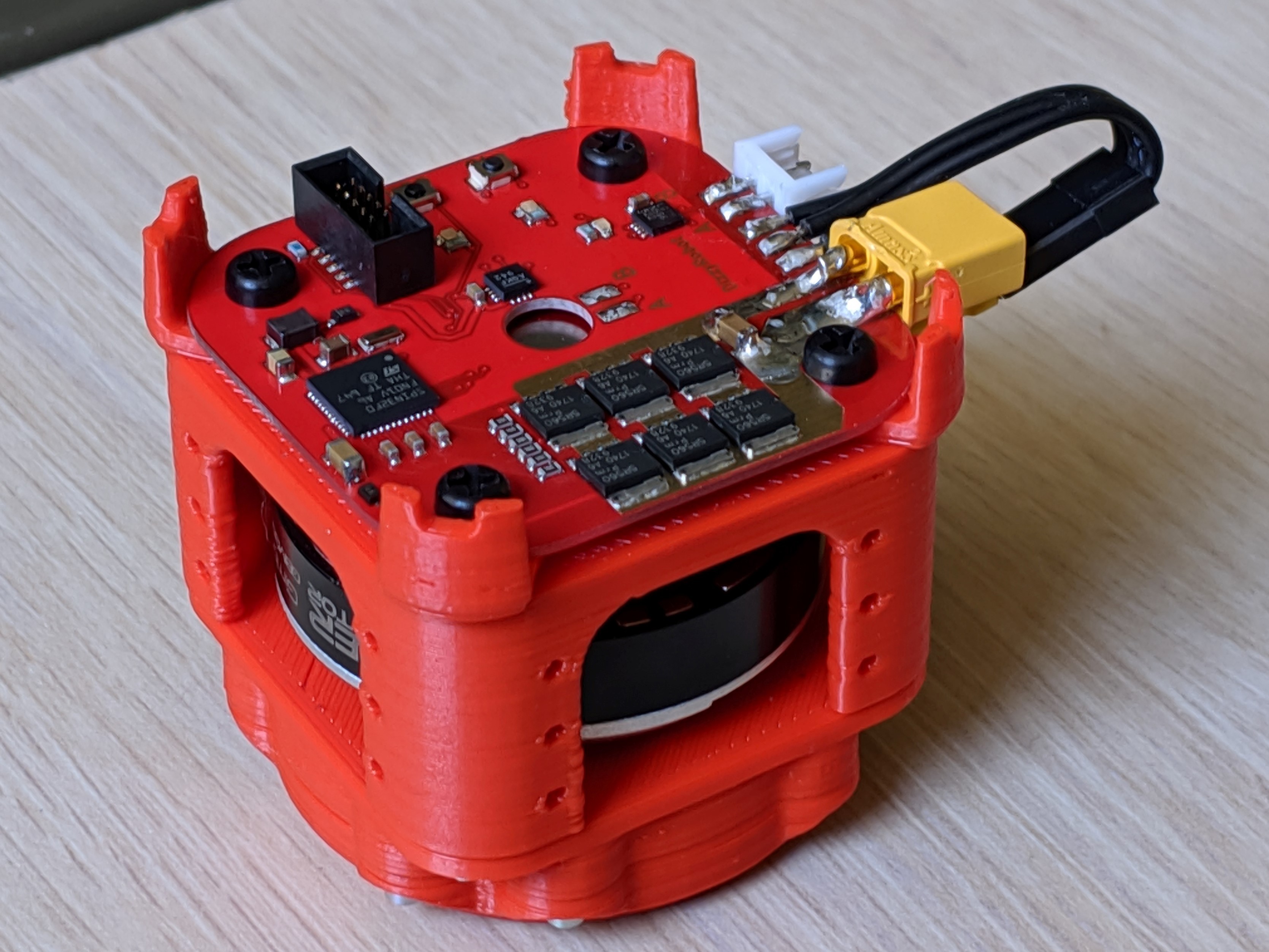
Once I decided to go with the DirectServo , I redesigned both the gearbox and motor enclosure to make it modular and to solve some persistent mechanical issues. Mainly that the load path through the gearbox could only withstand loads that didn't apply off-axis torques (leading to exploding gearboxes :( ), and that getting smooth predictable movement with the imprecise 3d printing of gear teeth was a continuous challenge. Moving to a Herringbone gear pattern solved the printing smoothness/yield problem, it turns out the pattern is much more forgiving with printing defects than the typical spur gear pattern. For the load path issue, I finally broke down and added 6705 Thin Section Ball Bearings (25x32x4) under the hood of each gearbox to redirect the load. The bearings are more expensive than I'd like at $15, but the final gearbox is incredibly robust as a result. Another benefit of adding the bearing was that I no longer needed an extra supporting enclosure on the outside of the gearbox. Here is a picture of the cross section of the new design:

The final cost for one of these 3d printed torque controlled gimbal motors is about $74 . That's $15 for the bearing + $38 for the DirectServo + $18 for the gimbal motor + $1 for the encoder magnet + ~$2 in fasteners and filament.
The dimensions are 47mm x 47mm x 47mm.

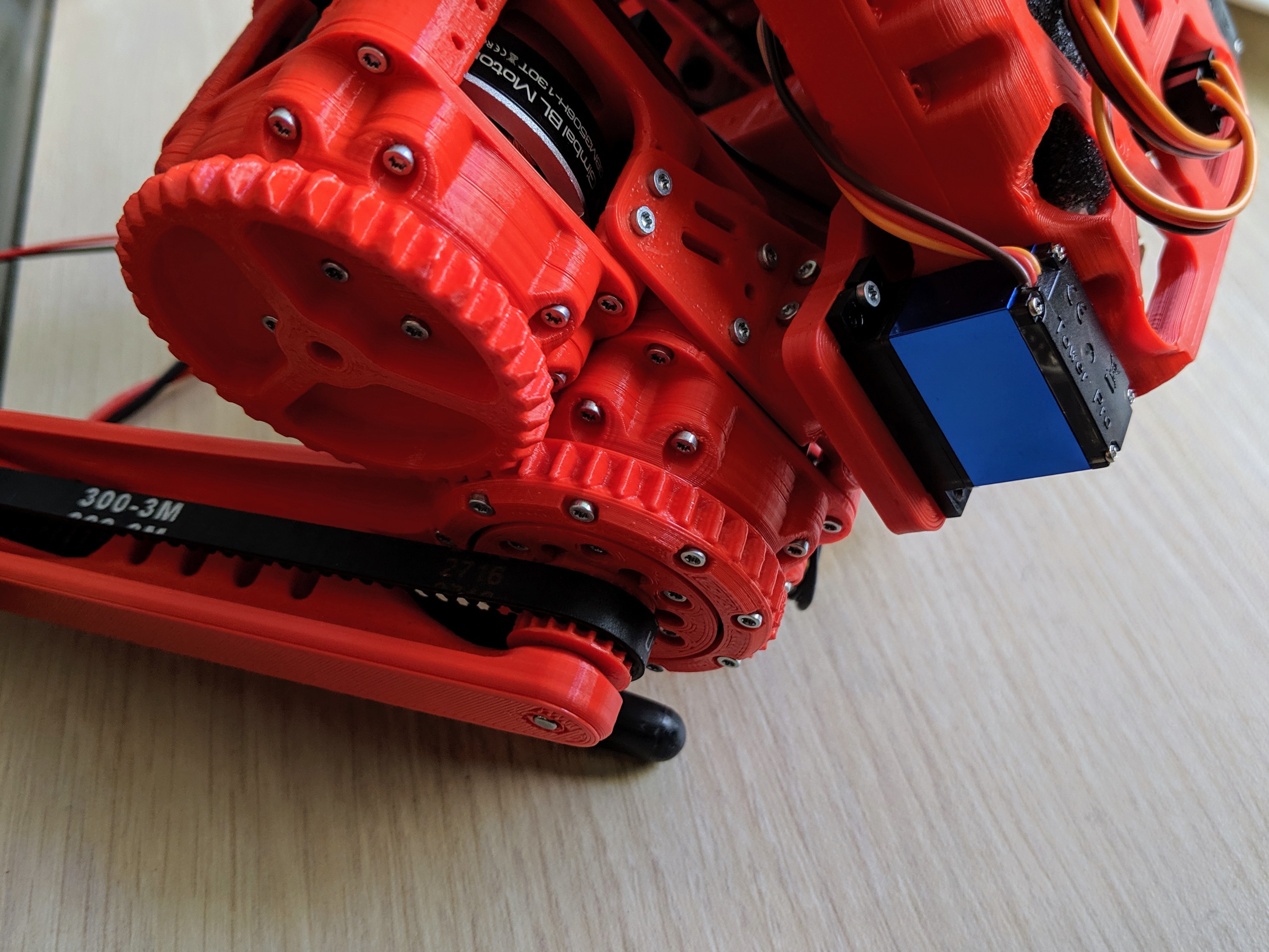
I also redesigned the legs, so that they were supported on both sides of the pulley all the way to the feet, which got rid of the last bit of backlash/flexure I was experiencing.
For the torso, the previous design had a large moment arm on the servos which created too large of a torque for the servos, and so in an effort to make the hip's side-to-side pivot point closer to the front-back rotation point (reducing the forces on the hip), I redesigned that as well.
First by trying a double pivoting linkage design, as seen here:

However, as you can see, that resulted in a lot of backlash and therefore vibration. The linkages also added complexity, and because the servos were located between the legs, it forced the legs to move apart, which is not ideal for a walking gate. So I removed them in favor of a more rigid direct servo mount design on the back of the robot:
As well as reinforced the centerpiece and beaglebone mounting plate, essentially combining them and making the center more tube-like to reduce the torsional flexure I was seeing. You can see the final design here:
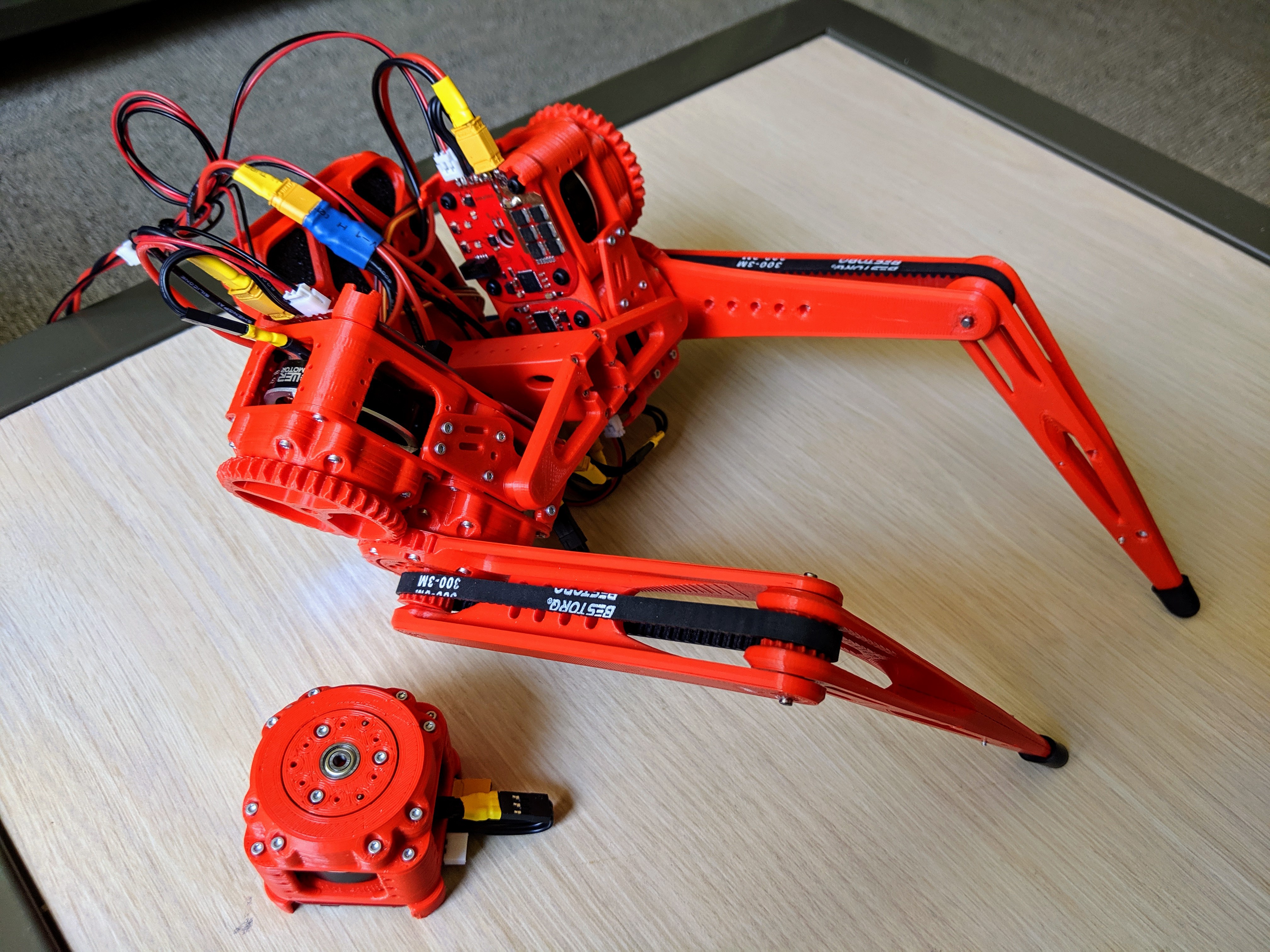
All in all, I've very happy with how rigid and durable everything turned out, and especially with how quickly the legs can move as well as their torque when given 24 volts.
My work going forward will be in setting up a testing apparatus and working on software to make it walk/jump/move. Eventually I would also like to print some clear and thin plastic protective shells to cover the moving parts and protect against falls.
That's it for now. Thanks for looking!
Discussions
Become a Hackaday.io Member
Create an account to leave a comment. Already have an account? Log In.