 Jarrett
I'm a huge fan of clever mechanical linkages.
Last year, I wrote a tool to help out with that:
https://github.com/JarrettR/Stagger
The inspiration is this Disney video / paper:
Just inspiration though, I'm sure I went in a completely different direction than they went.
Anyway, my tool is very incomplete, and kinda hacky, but the gist of it is:
I can give it a series of parameters, and it will calculate how the two-bar linkage of that system works. And, if you like, animate it.
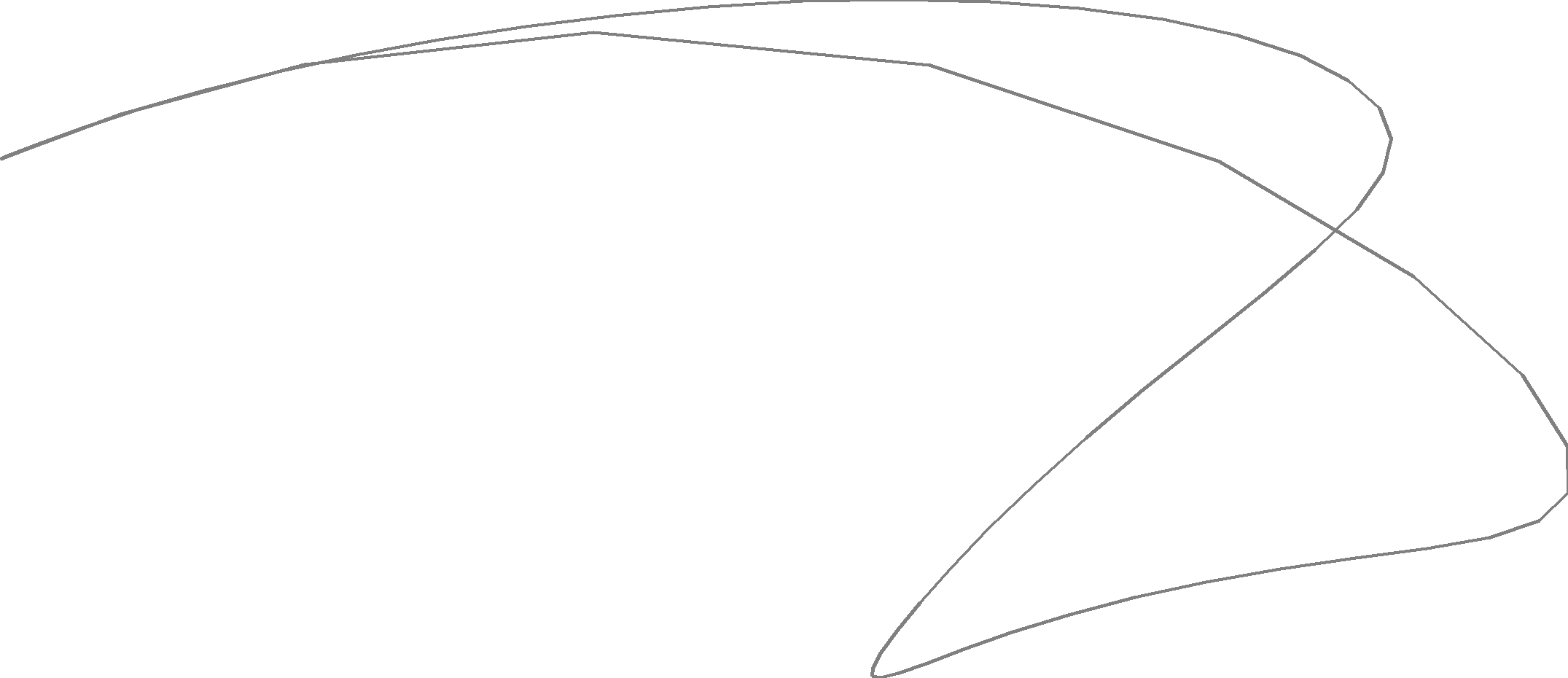
That black path on the end? That's the bit we really care about, though.
So we can give my tool a set of limits to vary within the parameter, and it will generate the entire set of permutations, throwing out the ones that don't make physical sense.
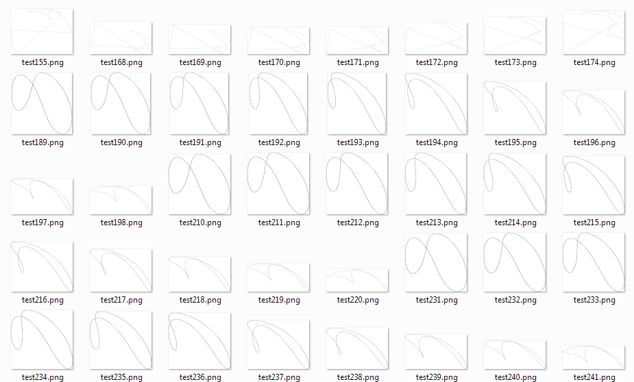
(It can also export to more machine-friendly formats, like an SQLite database)
From there, we can choose a path that we like, grab the critical parameters, and leave the tool.
For example, in this particular sample set, I like Test 324.
It has a set of parameters like this:
self.bar1.length     35
self.bar1.joint      30
self.bar2.length     40
self.drive1.x        15
self.drive1.y        3
self.drive1.r        10
self.drive1.speed    6
self.drive1.initial  0
self.drive2.x        15
self.drive2.y        22
self.drive2.r        10
self.drive2.speed    3
self.drive2.initial  180
And very very quickly dumping that into SolidWorks:
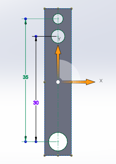
We have an assembly!
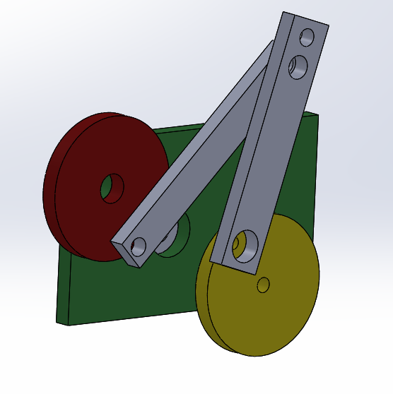
And it can be mated together!
That highlights a problem with this method! The movement looks like balls. The flick at the top of the movement compared to the speed at the bottom is very much not what I want. I ran the in-tool motion animation feature, but it was animated too fast to identify the speed disparity. I will slow it was down and be more careful in the next test.
Discussions
Become a Hackaday.io Member
Create an account to leave a comment. Already have an account? Log In.