Alexey
v1.0 update
For v1 I made two major changes.
Disable AP/STA mode
After one year of use it proved to be pretty reliable with one exception: due to "gateway" mode, when handset unit served as an access point for outdoor unit and as a client for indoor WiFi, it would occasionally loose connection between handset and door for 10-30 minutes. Probably it had something to do with connection to home network, router switching channels, renewing lease or whatever and ESP trying to reconnect. When home router was powered down, handset and door would not connect at all, as ESP would constantly search for home network. When connection to home network was disabled this problem when away completely. As pretty much only purpose of connection to home network is adding/deleting keys, which I didn't do for entire year, I decided to ditch it.
Instead of MQTT for managing keys I've added a simple web-interface powered by Vue.js and Bulma.css.
Switch to i2s DAC
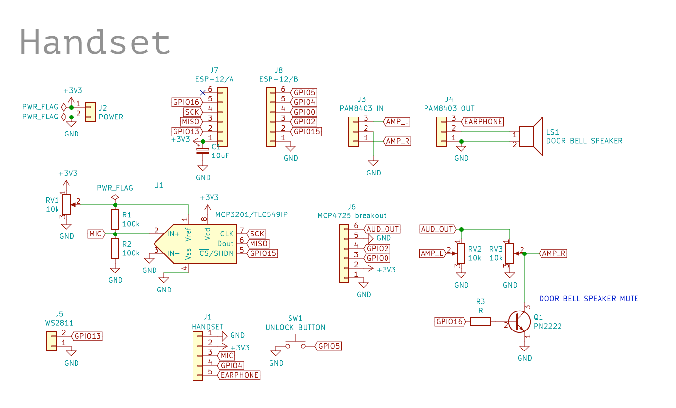
I got rid of MCP4725 DAC and replaced it with i2s-compatible PT8211/TM8211 16bit DAC. I connected MCP3201 CS and TM8211 WS pins, as a result I can read sample from ADC and send sample to DAC in the same SPI transfer, which happens in background via hardware peripheral. I've update ISR handler to read previous transfer result first, then start next transfer and return immediately.
Ditching MCP4725 requiring software i2c allowed me to run esp8266 at normal 80MHz, which contributed to stability as well.
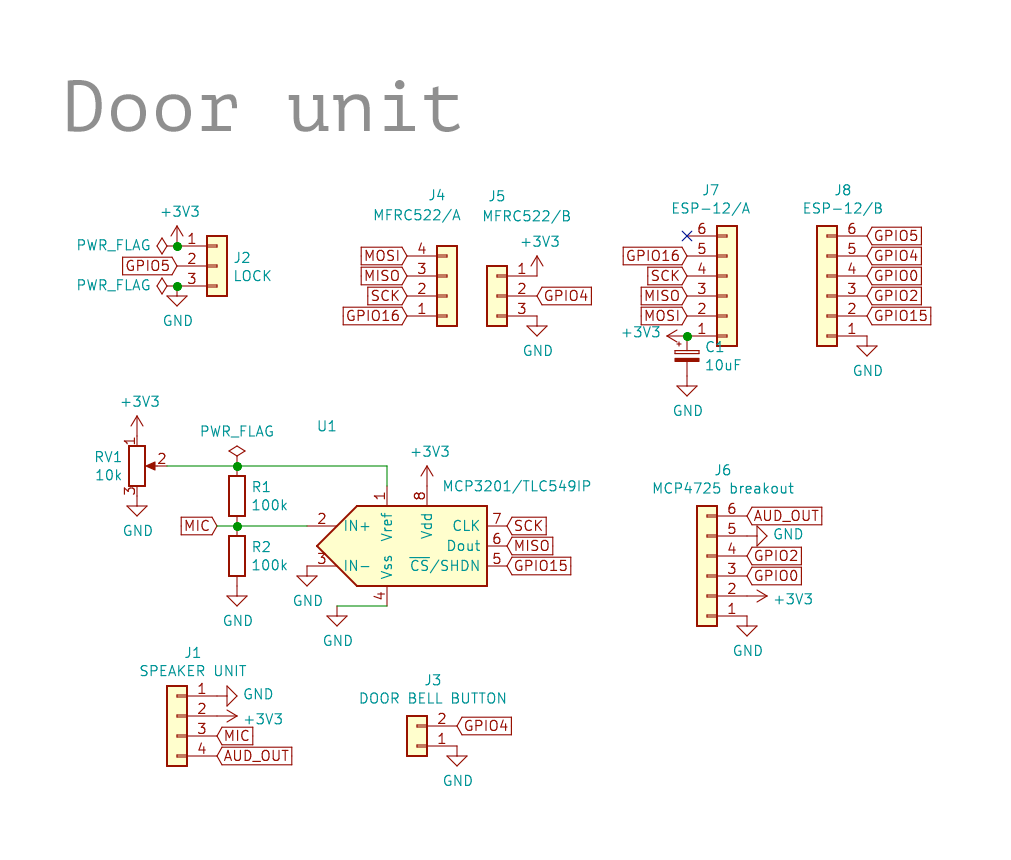
I got rid of long analog connections by moving ADC and DAC to speakerphone, now all the communication between ESP and speakerphone panel happens via SPI. For this purpose I designed and etched a small board (gates-v1-speaker.kicad-pcb) for ADC, DAC ICs and MFRC522 connector.
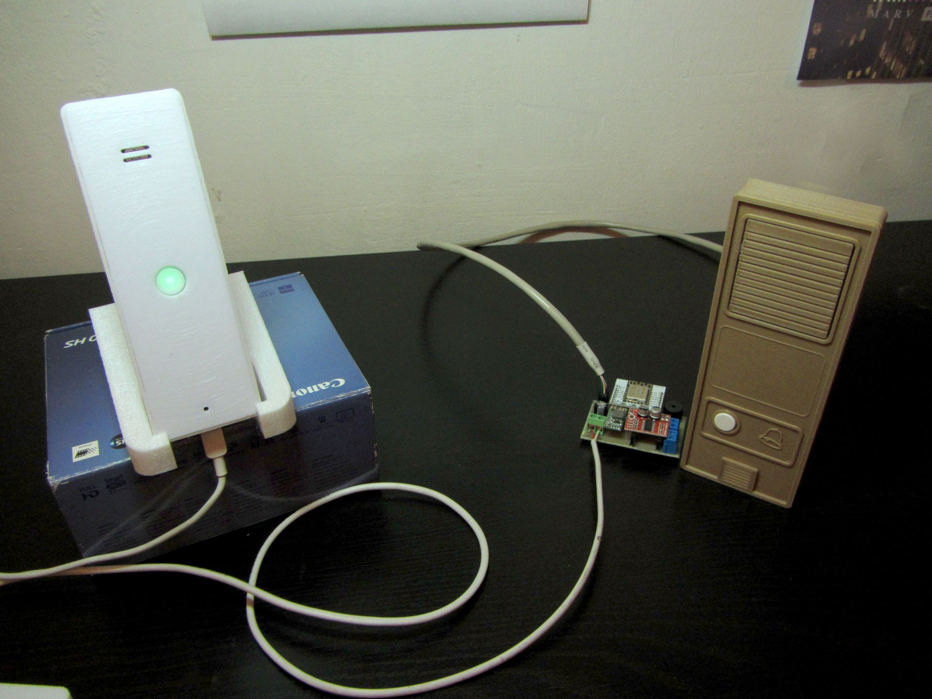
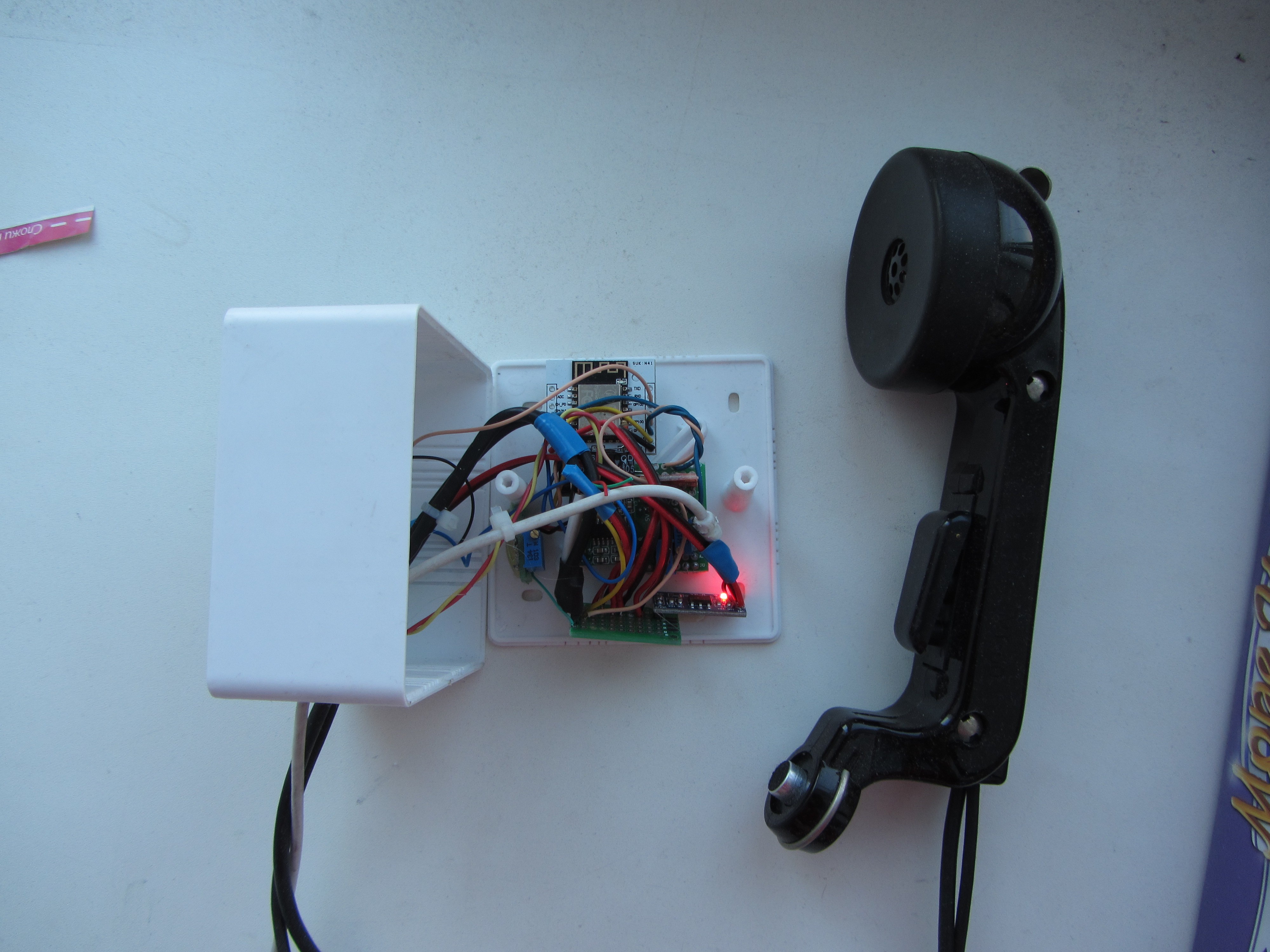
Handset
Now all components of indoor unit are encased in handset. Pickup/hangup triggered with reed switch in the back of the handset and a magnet in the stand.
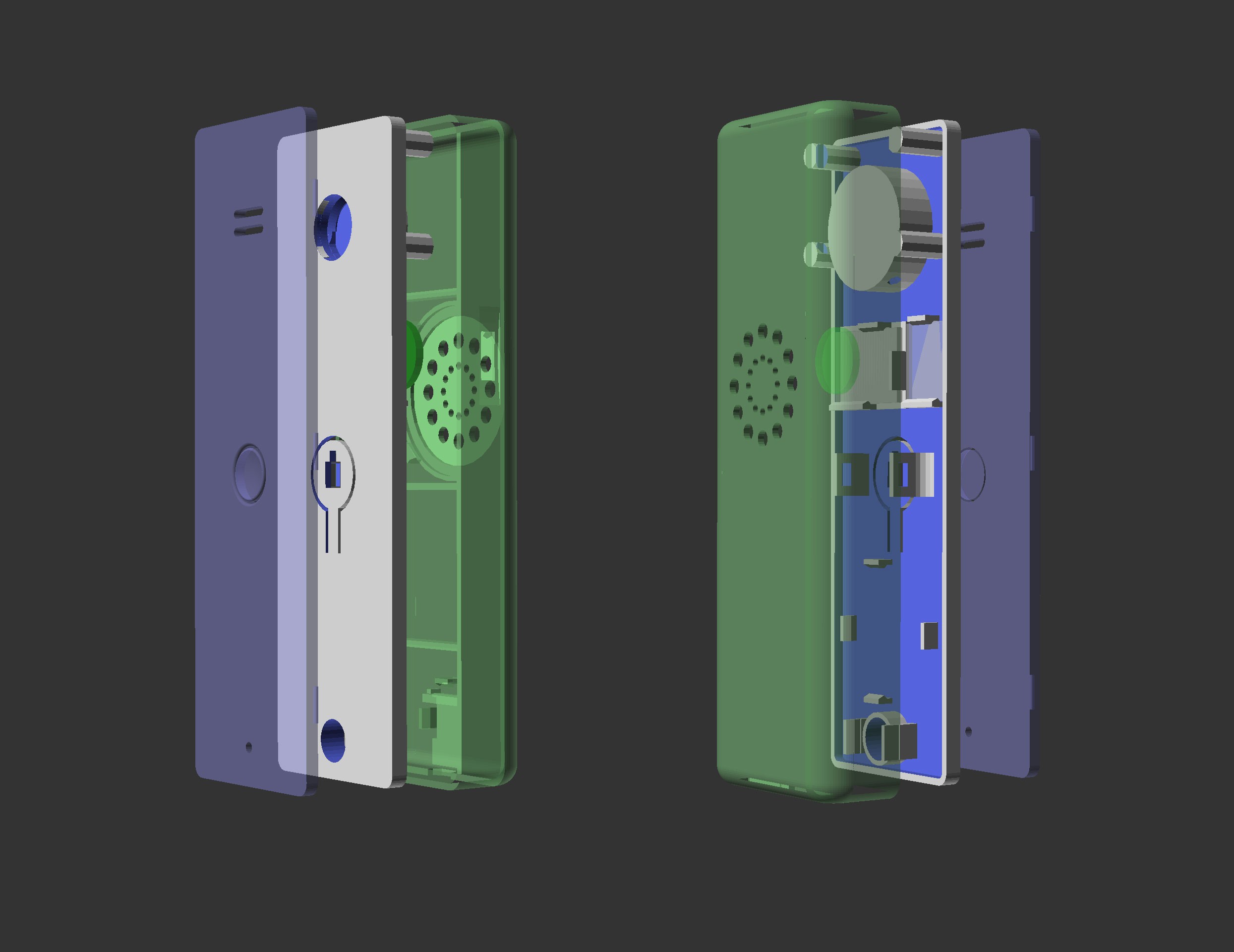
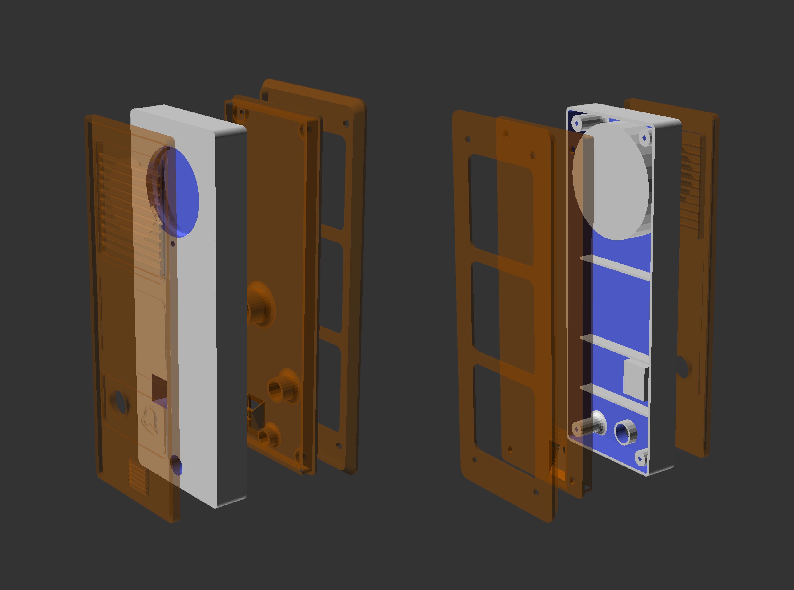
3D-printed enclosures
3D-printed parts were designed in OpenSCAD.
Some details
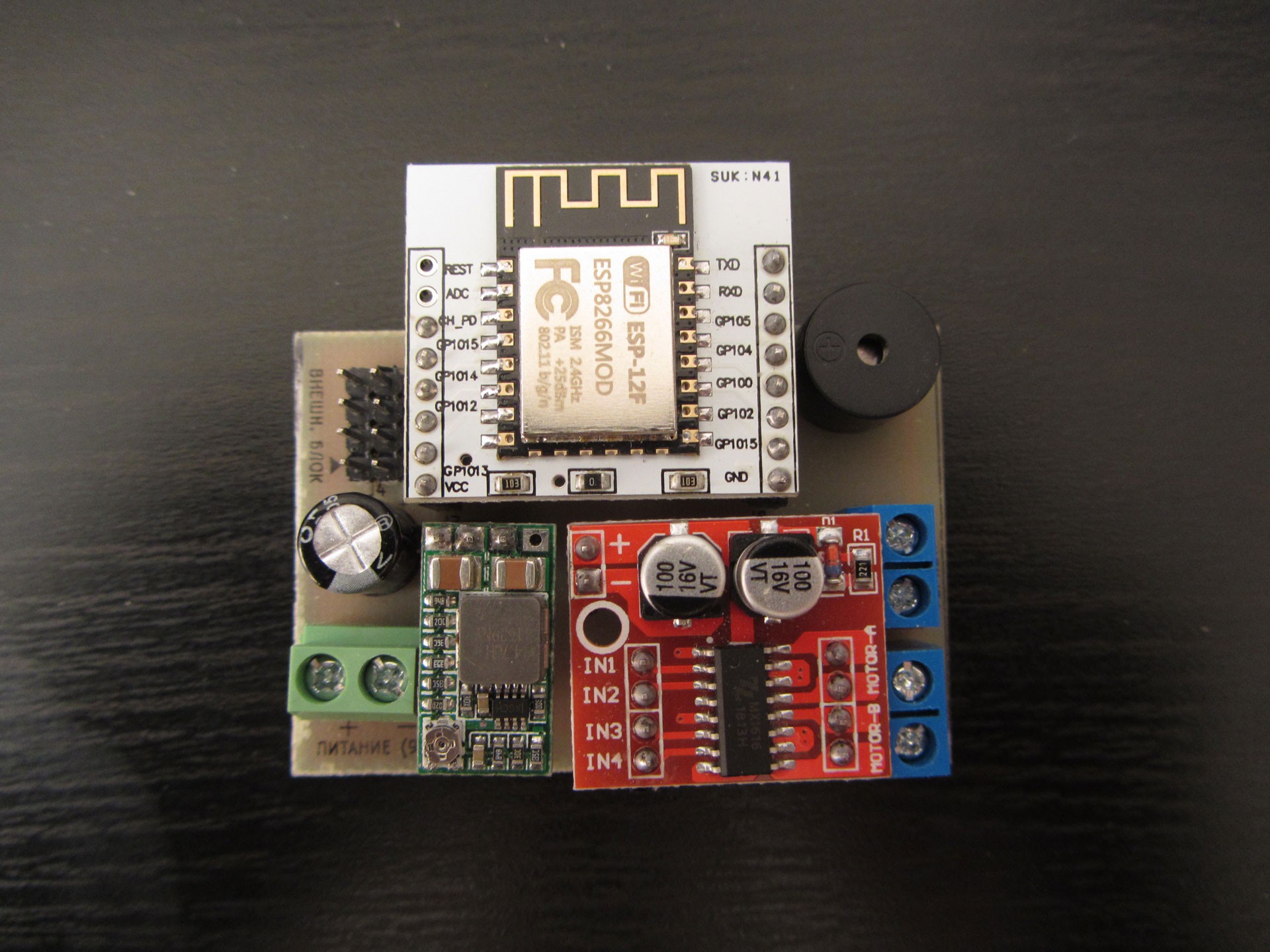
Main board of the door unit:
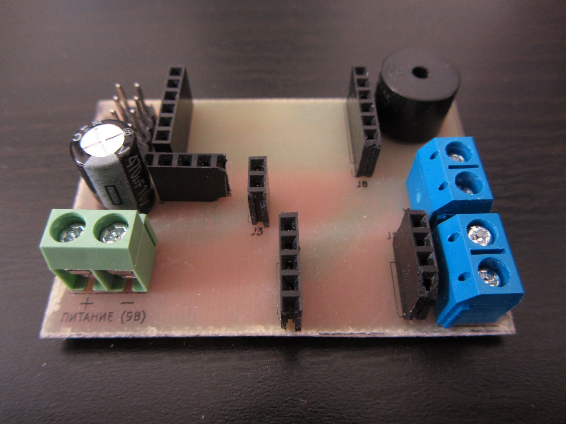
Main board populated with breakout boards: ESP-12, DC-DC converter, motor driver.
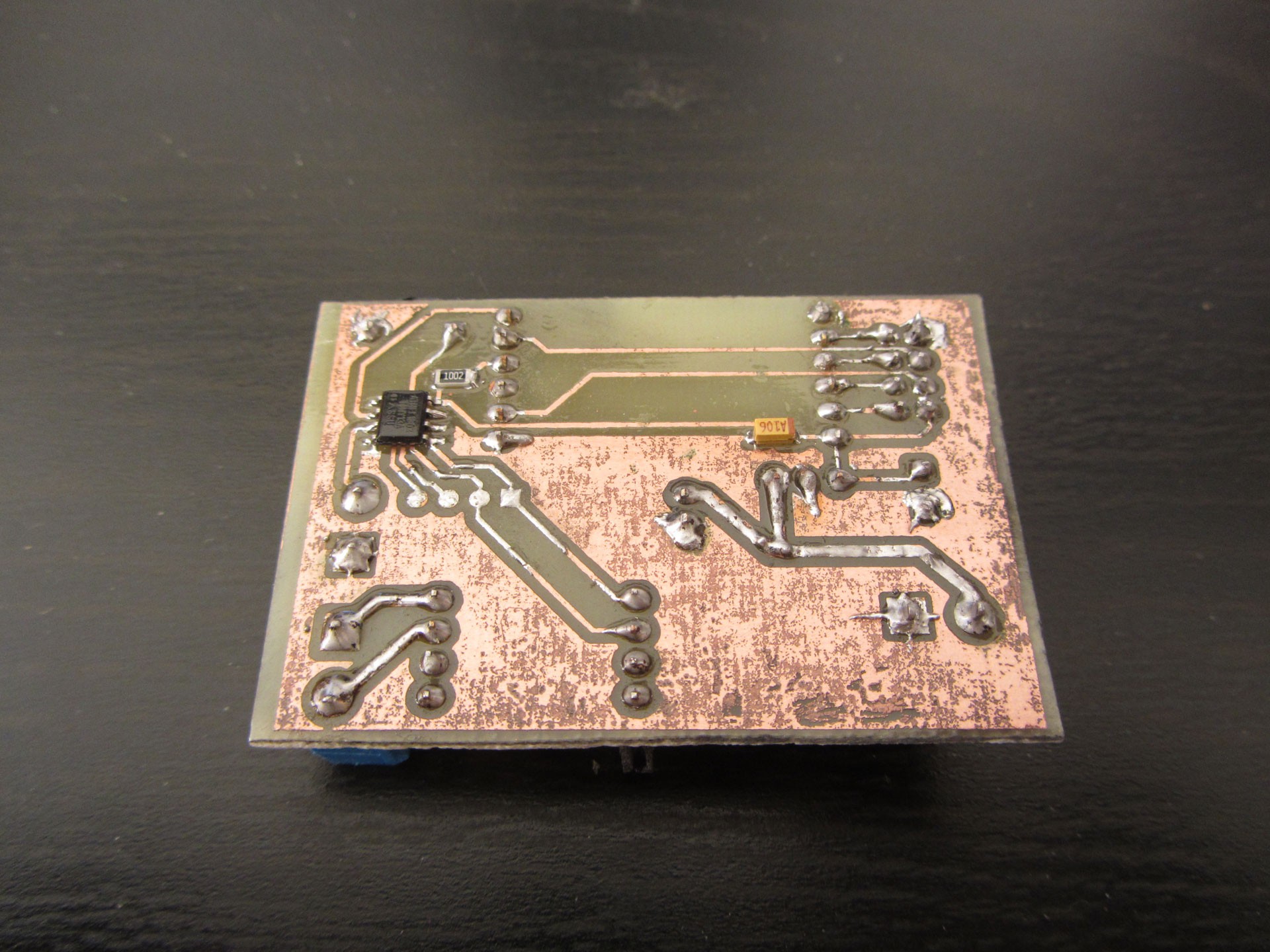
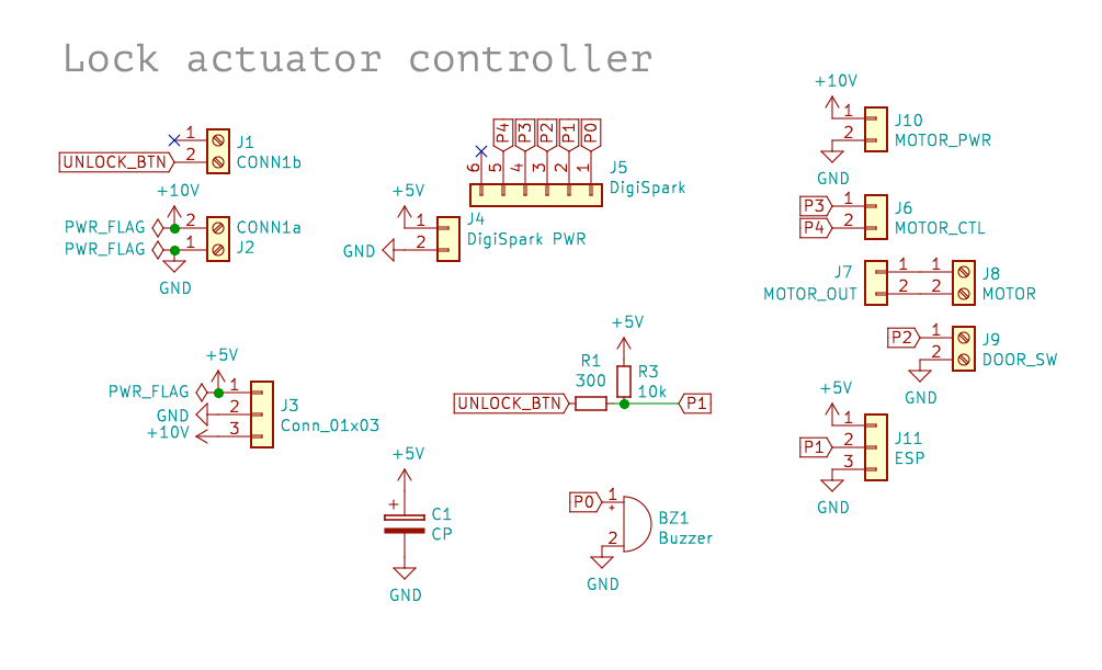
Lock controller moved to attiny13 on the back side:
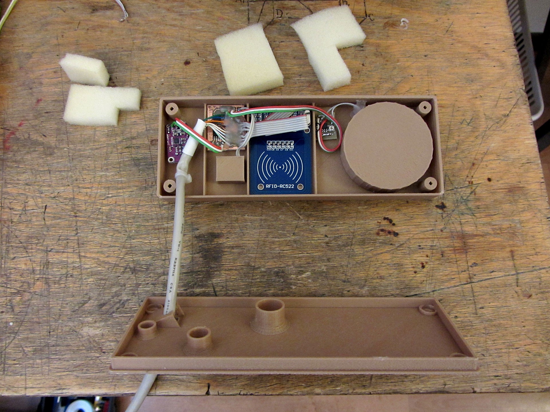
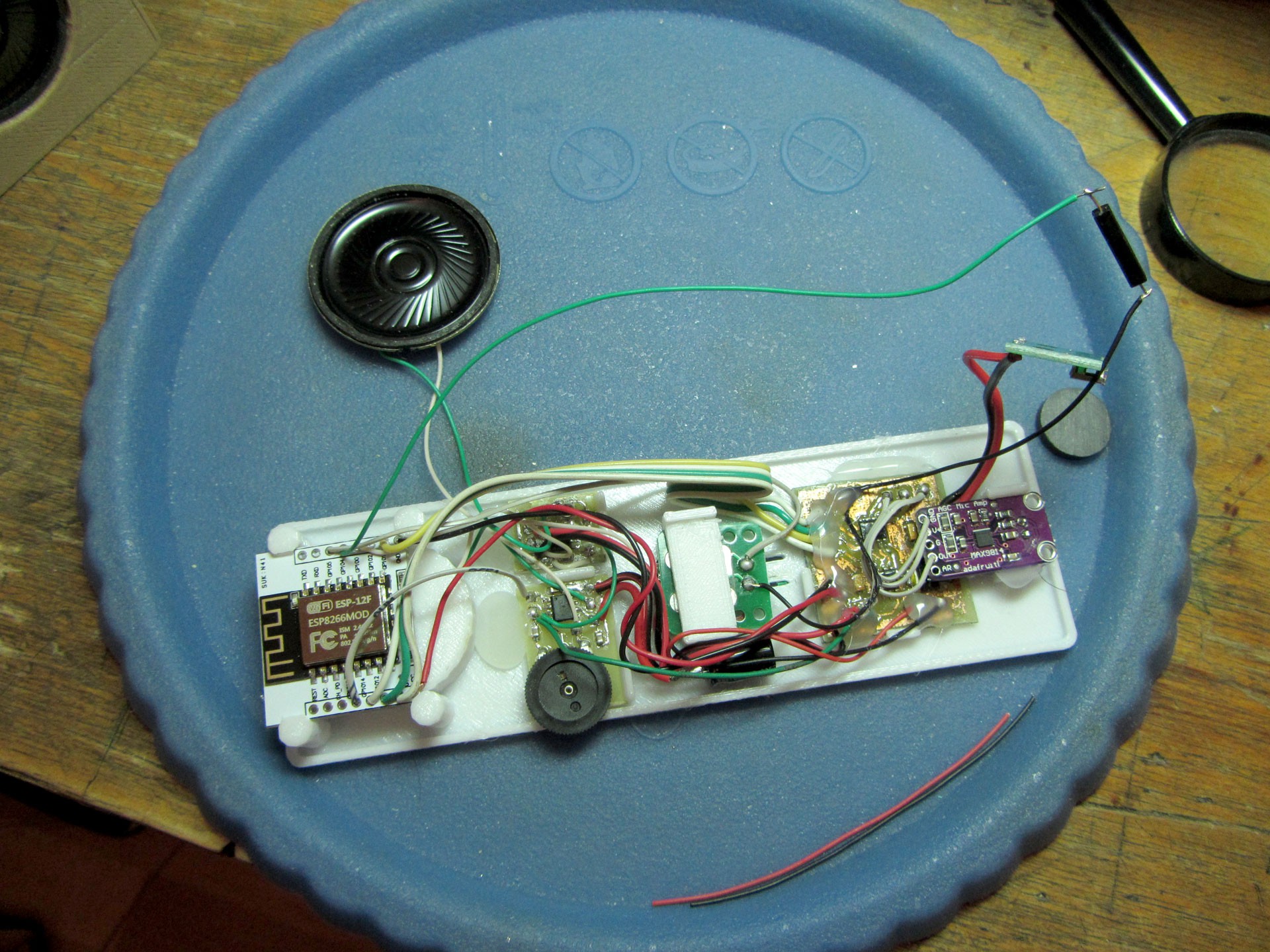
Layout of components in the speakerphone panel:
Layout of components in the handset:
Ringtone speaker, reed switch and microUSB port mounted on the back cover.
Original (v0.1) build
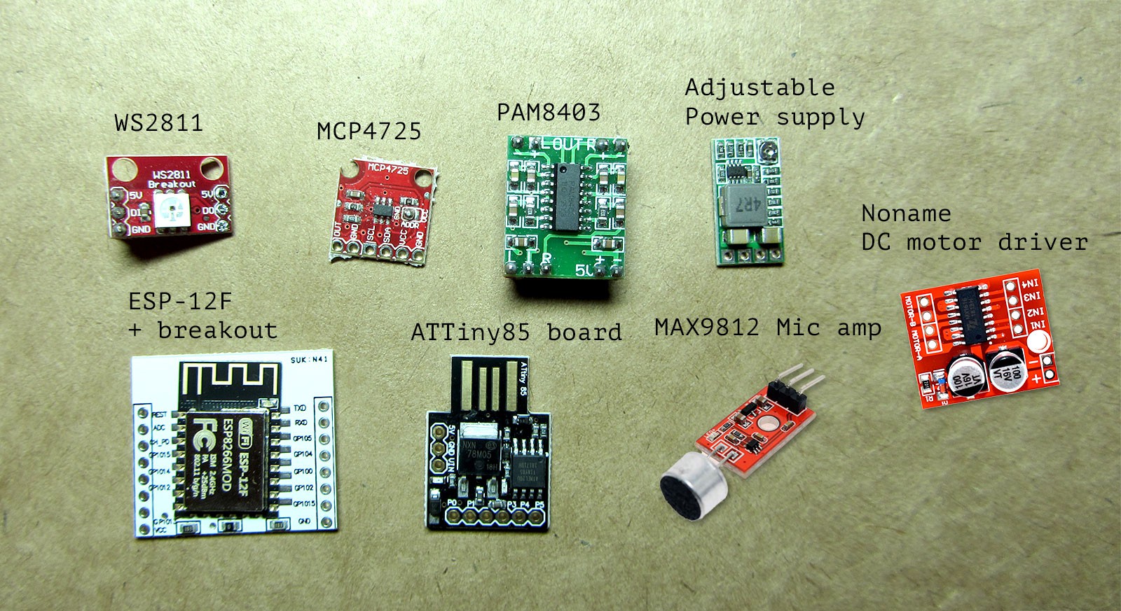
As this is one time build, it's based on breakout boards/modules from ebay/aliexpress soldered to a perfboard.
Some breakout boards/modules utilized in this project:
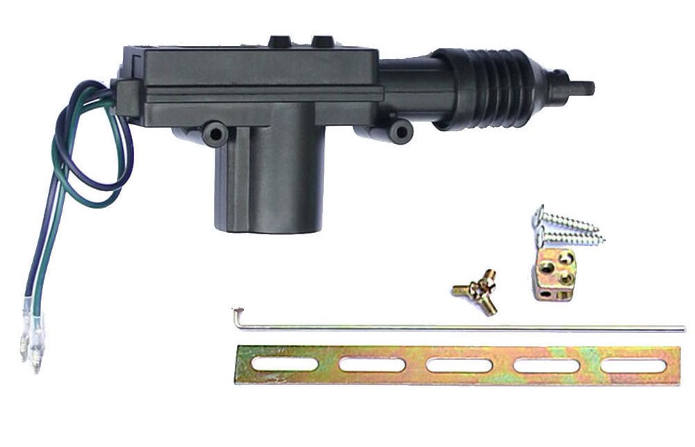
Power door lock actuator unlocks a simple door bolt. Reed switch and a magnet mounted on the frame used as a door contact switch.
This is the door lock actuator I'm using:
Initially it was very simple lock controller with single "unlock" button. Voice communication and RFID reader added later.
Audio quality turned out to be pretty good. There is no feedback noise due to earphone on the handset side. To get rid of digital noise and echo use shielded cable for microphone signal.
One of the reasons I decided to build this thing is to find some use for this old army phone handset I had, it has this very convenient switch I'm using as "connect" push button:
Network setup
Handset unit acts as both client and access point. It creates access point used by door unit and connects to existing WiFi network as a client to communicate with home assistant via MQTT broker.
Door unit establishes connection directly to handset unit AP using hardcoded credentials. Handset unit uses hardcoded credentials to create soft AP and WiFiManager with captive portal to configure connection to existing network.
Door unit and handset communicate using bare UDP packets and simple 1-byte commands.
There are two copies of known keys, main on the handset unit, managed via MQTT commands and a copy synced via UDP on door unit.
There are several reasons behind this setup:
1. Handset unit effectively acts as WiFi range extender.
2. I don't like having device with no encryption and easily accessible by any stranger directly connected to my internal network.
3. Door phone main function should not depend on any other hardware.
All management done in Home Assistant via MQTT.
Handset subscribes and publishes to several topics:
| Topic | Payload | Description |
| yard/gates/lock/set | LOCK/UNLOCK | Lock control |
| yard/gates/lock/status | LOCK/UNLOCK | Lock status |
| yard/gates/keys/add | [UID];[COMMENT] | [UID] - RFID uid in hex format - XX:XX:XX:XX [COMMENT] - e.g. key holder |
| yard/gates/keys/delete | [UID] | Delete key, format is the same as for adding, but without comment |
| yard/gates/keys/list | ALL | In response to this messages handset unit publishes list of known keys to "yard/gates/status" topic |
| yard/gates/status | This topic used to display status notification. e.g. "Connected", "Unknown key scanned" and list keys. |
This is what control group looks like in Home Assistant UI:
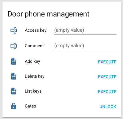
Add/Delete/List operations implemented as scripts with "mqtt.publish" actions. Lock configured as standard MQTT lock component.
Home assistant config can be found in github repo with the rest of code.
Schematics
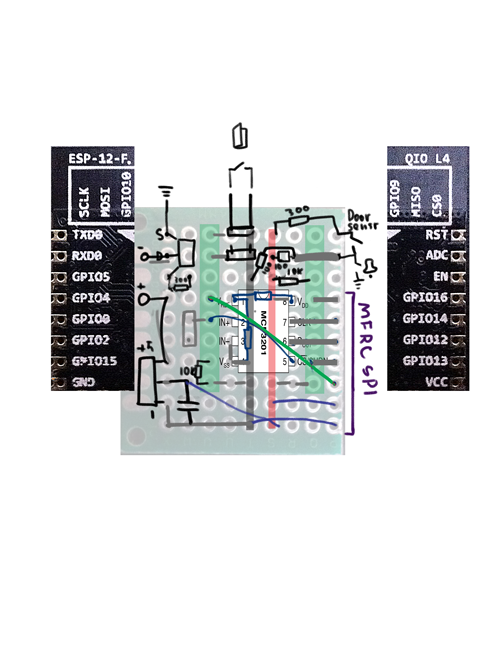
Some rough schematics made in KiCad
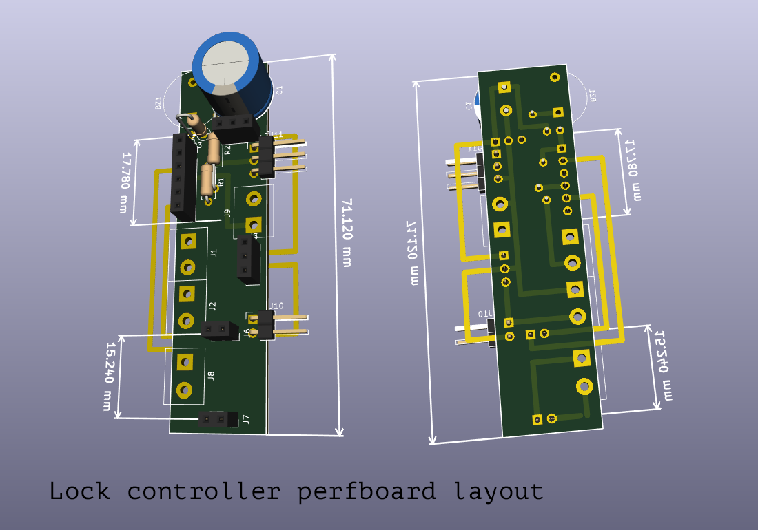
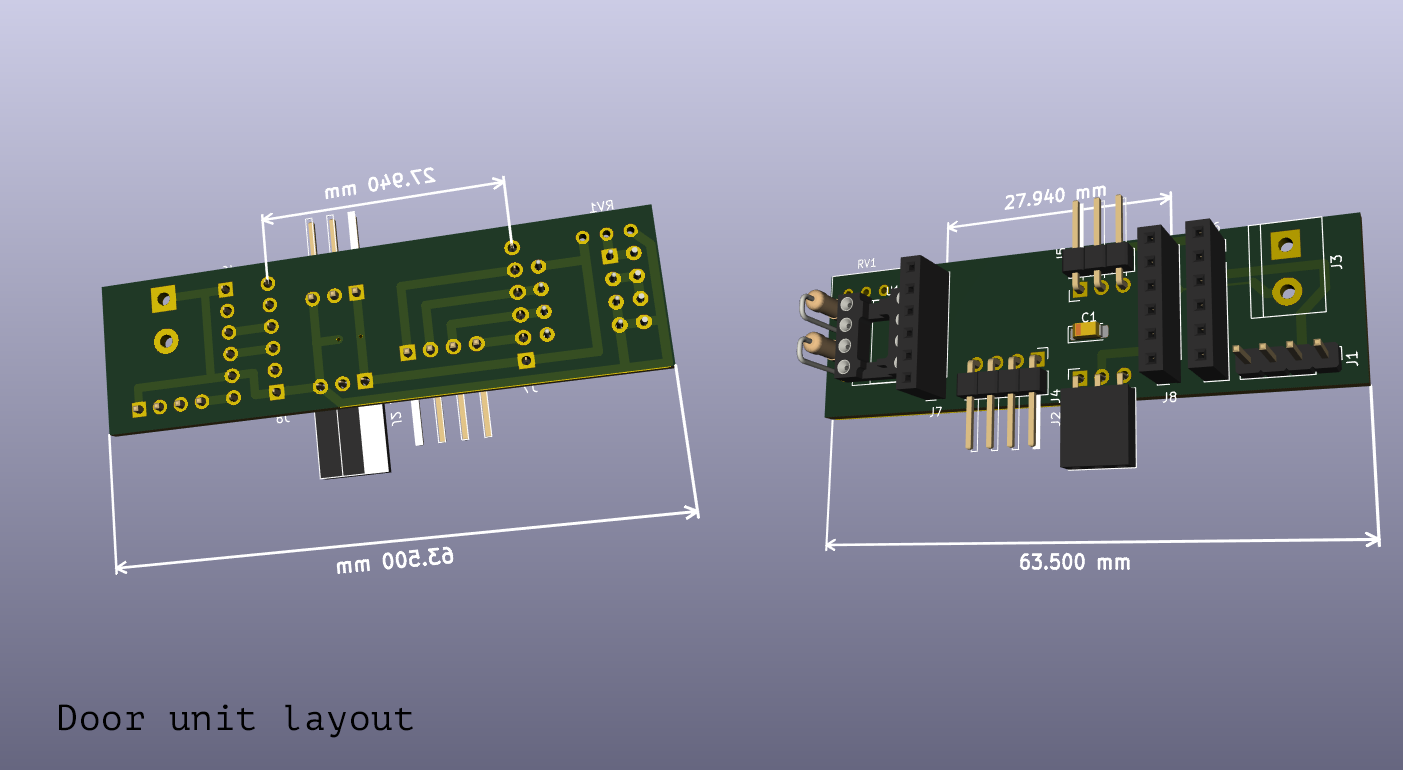
Perfboard layout
To make things a bit easier I designed "PCB"s in KiCad with grid set to perfboard spacing. Traces placed on front layer and outside board meant to be jumper wires when actually soldering this stuff.
Handset wiring was pretty straightforward, so I slapped it together with wires (and it looks horrendous as a result).
If you think those are bad, you didn't see my initial "schematic" :D