 David Pye
I have been running a few experiments with my IN-12 nixies this evening, to try and decide how best to set pulse voltage/current.
The IN12 Soviet data sheets do not specify any details for pulse operation, but the side-view IN14 nixies do. They specify similar direct drive parameters, so I have extrapolated these to pulse operation.
I am aiming for a strike voltage of 190V, and pulse current of 8-13mA. However, there's no mention of how to calculate an anode resistor here.
So I have decided to do it experimentally (and using some helpful advice from the neo-nixie google group!)
In order to measure pulse current, you need an oscilloscope, and measure the voltage drop across the anode resistor during the pulse. From this, and the known value of the anode resistor, you can work out what the pulse current through the resistor (which also flows through the nixie) will be.
From my Rigol scope, using a 3k9 anode resistor, I got this:
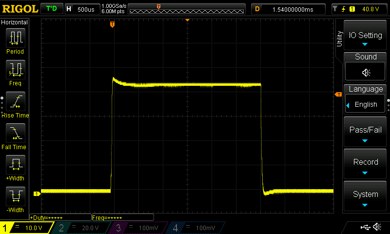
Using a strike voltage of 200V, and that value of anode resistor, the voltage drop across the resistor during the pulse is ~43V. With another nixie tube, it was 50V.
So, using Ohms law, a current of between 11mA and 12.8mA is flowing, so this is about right. This means the sustained voltage across the tube (once it has struck) is around 150V.
So, here is a scope plot of the voltage across the tube during the pulse (note the Y axis scales are different!)
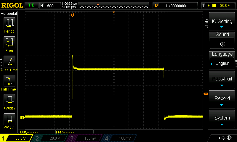
So, you can see that at the start of the pulse, the full 200V appears across the Nixie, it strikes, and pulls the voltage down to the sustain value (which, with the anode resistor dropping 50V), is 150V as expected.
For interest, i decided to zoom in on the first part of the pulse, to better visualise what happens when the nixie strikes:
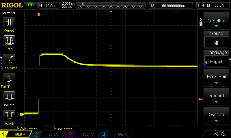
So, you can see for about 18microseconds, the nixie doesn't conduct, then over the next 12microseconds, it starts to ionise and conduct, and by 30microseconds after the start of the pulse, it reaches steady state.
So, I'm fairly happy that my anode resistor value of 3k9 is about right here, for pulsed operation.
I intend to produce some graphs showing current in pulsed mode for both IN12s and IN14s to aid other experimenters...!
David
Discussions
Become a Hackaday.io Member
Create an account to leave a comment. Already have an account? Log In.
Perhaps my next Nixie project will take advantage of momentary high-current pulsing, instead of being all safe with the rated continuous current spec :) Nice insight there Mr Pye!
Are you sure? yes | no
Hi Ken,
Thanks for the link - I have read his pages before, but it didn't help with the one issue I had here. How do you decide on a current limiting resistor for a nixie when you want a 13mA current pulse, rather than the 'standard' 2mA continuous duty current? The answer, it seems, is by experimentation, as the nixie datasheets do not include the data you'd need....
Are you sure? yes | no
I found this useful article some time ago: https://threeneurons.wordpress.com/nixie-power-supply/
Are you sure? yes | no