 Bree Hoffman
Chassis & Leg Design:
Shelly's chassis and leg assembly was spec'd out in OnShape. You can see the design here.
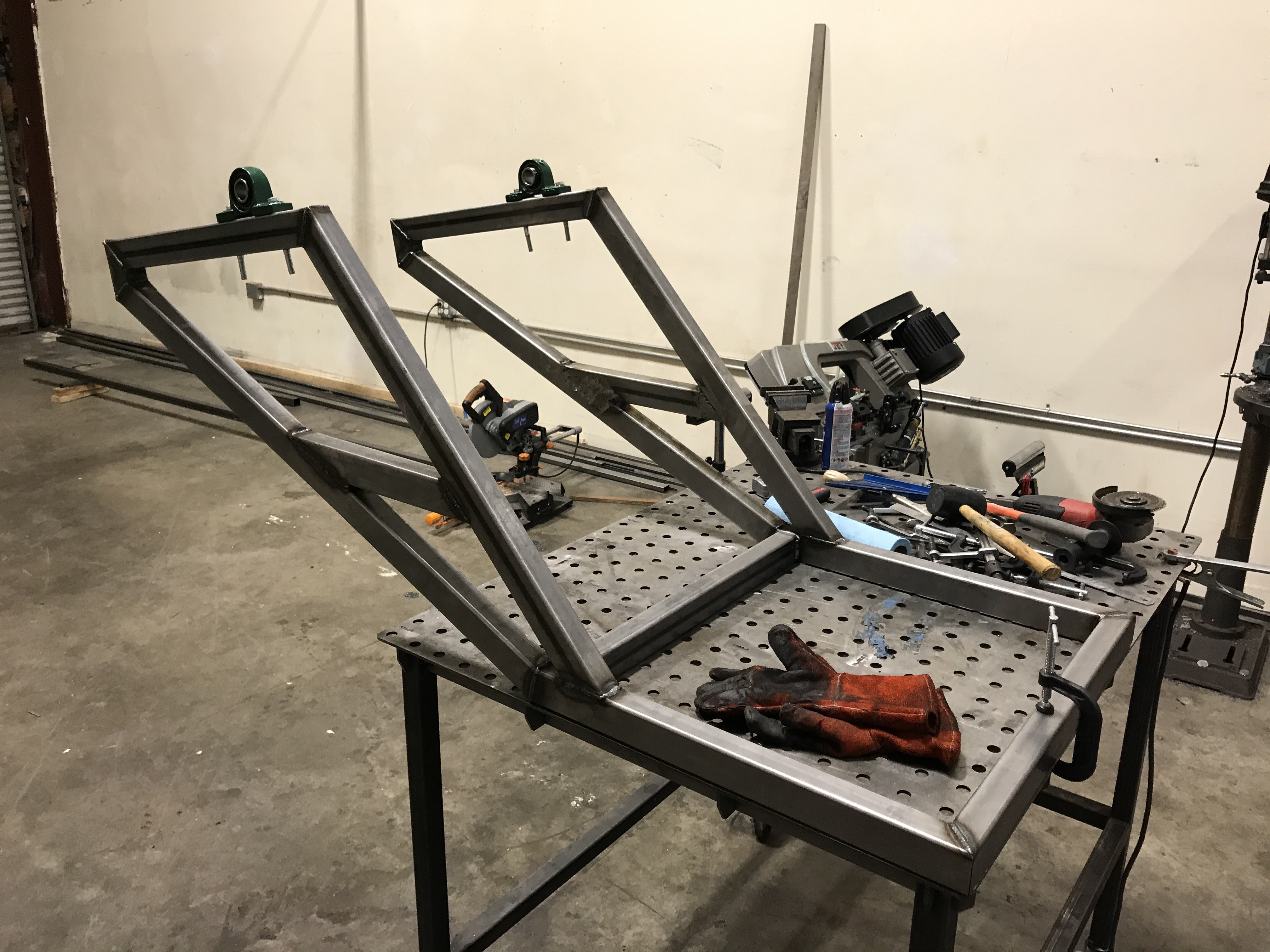
The main constraint's of Shelly's legs design are lateral rigidity, as well as overall assembly width. The ideal leg assembly would include 6 legs, not 4, however each leg needed to have enough lateral stability that it wouldn't buckle when all of the creature's weight was on 1-2 legs, and in order to accomplish the sculptural direction I was intending, I decided to stop at 4 legs. to obtain the correct width.
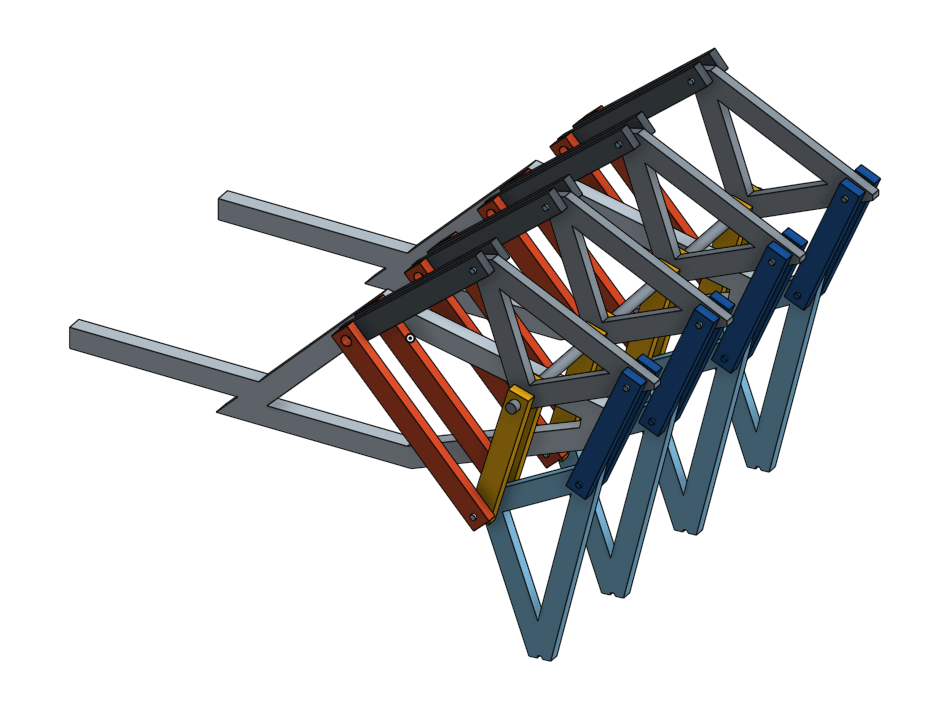
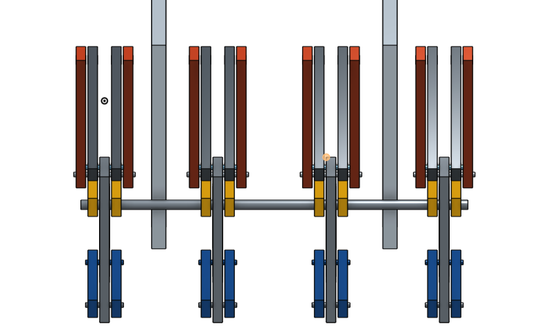
In order to achieve this stability, each leg it composed of 3 different co-planar leg-struts. Designing in OnShape allowed me to not only ensure each leg had sufficient stability (by making an assumption + using my design instinct), but also measure out how much specific distance would exist between each leg component in the assembly.
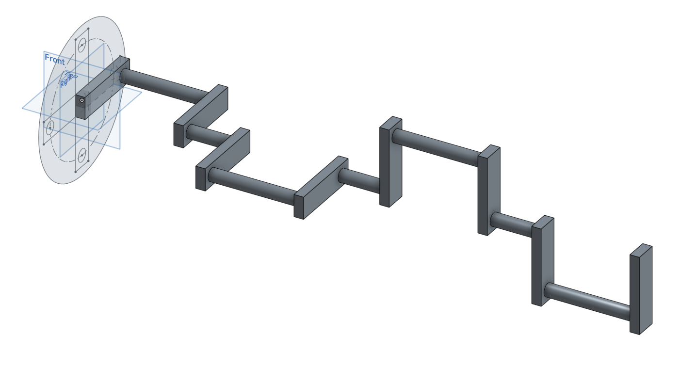
The crankshaft was designed independently.
And the final assembly was constructed to verify tolerances.
Here is a Google Presentation explaining the initial conception of Shelly + her leg design implementation. https://docs.google.com/presentation/d/12uXXUTTyd59Ykw1Y4nGj8KfAY9_r4Iwe6DVM3xkHPlI/edit?usp=sharing
Ultimately I abandoned the gas engine + clutch because it wanted to happily run at like 2,500 rpm. Shelly needed to get down to 250 rpm minimum, so my friend Andrew Renz helped me install an electric ebike motor. This allowed Shelly to actually propel herself at a reasonable speed!
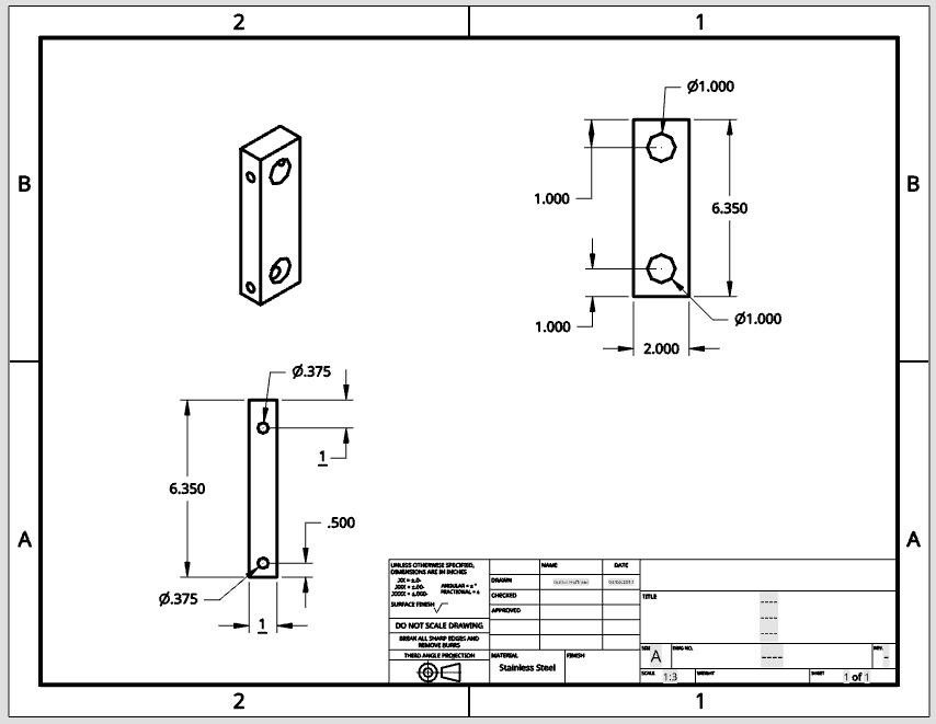
Crankshaft Fabrication:
My friend James Erd helped mill out the stainless steel crankshaft components used to push Shelly's legs. It's undoubtedly the corner-piece of this build, along with the motors/electronics. I have a ton of respect of Jame's process, knowledge, and machinery!
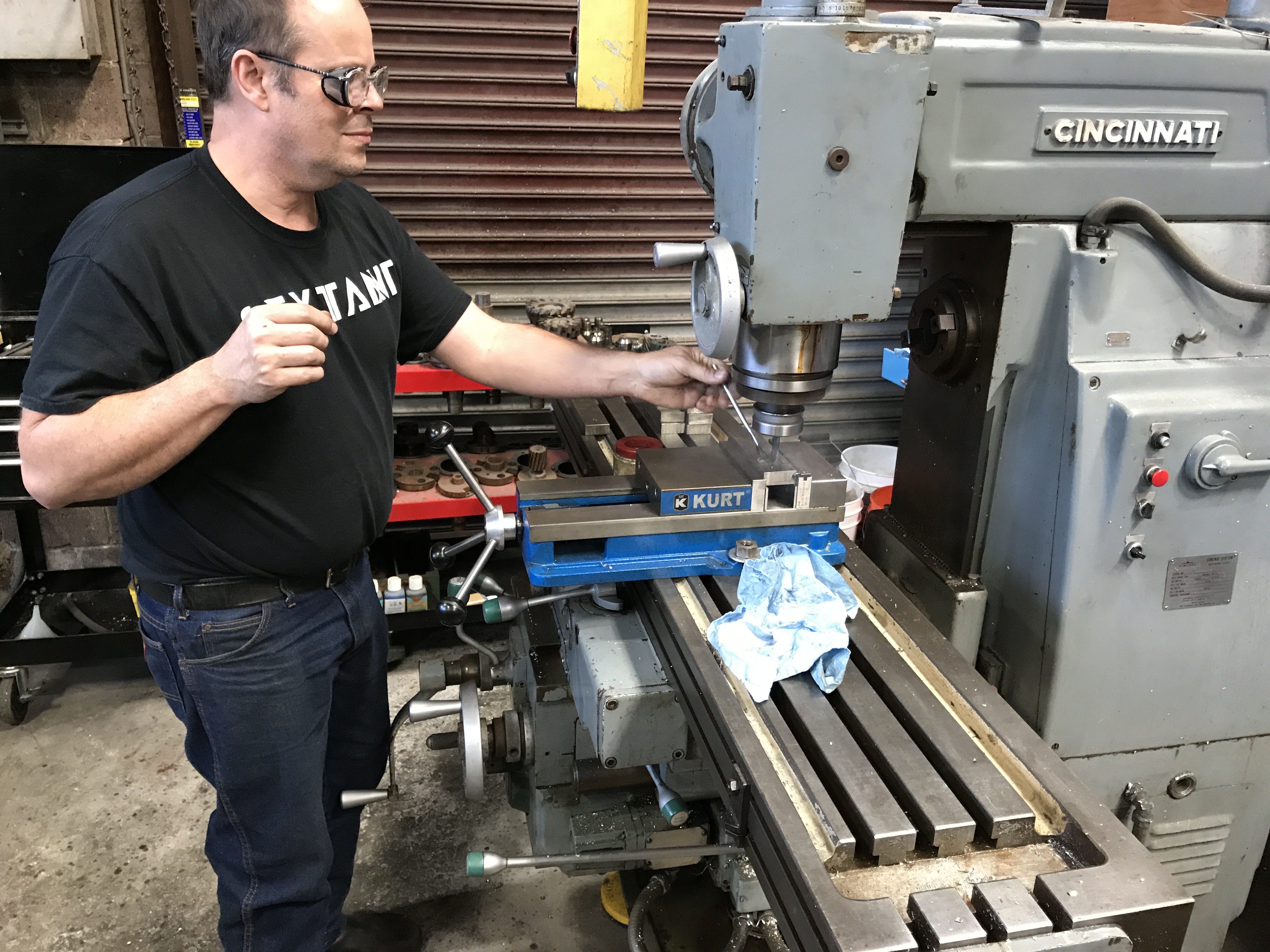
James taught me to use a rubber hammer instead of a metal hammer when assembling my tight-fitting metal components. It was one of the best pieces of advice I got on this project.
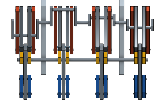
Leg Assembly & Articulation:
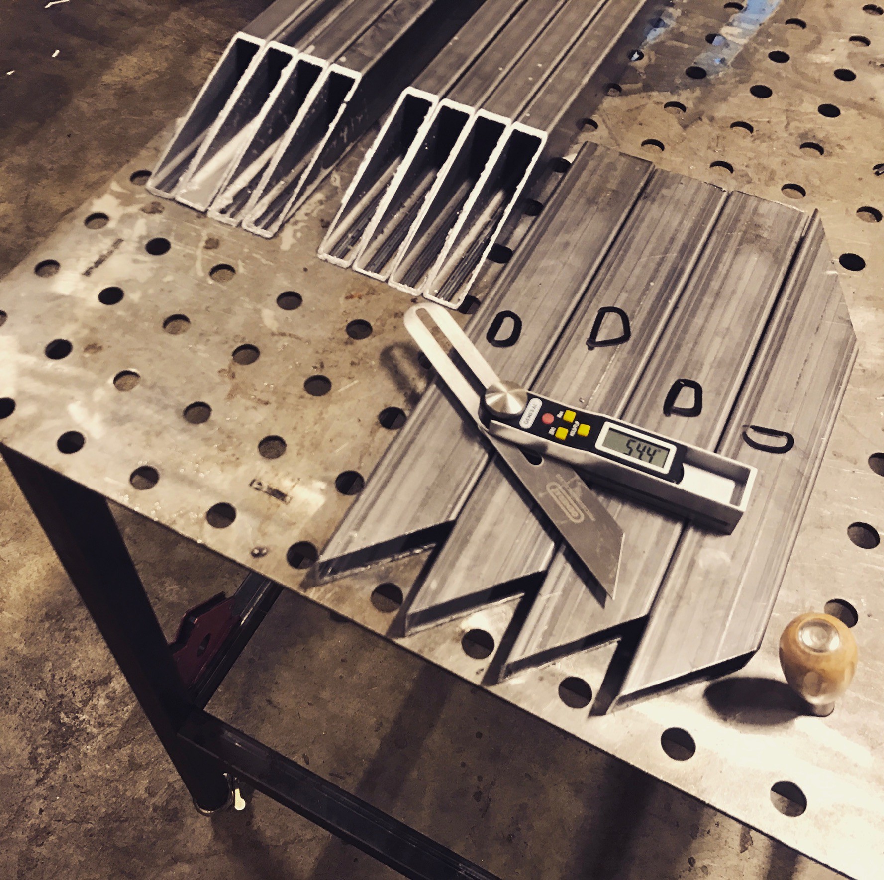
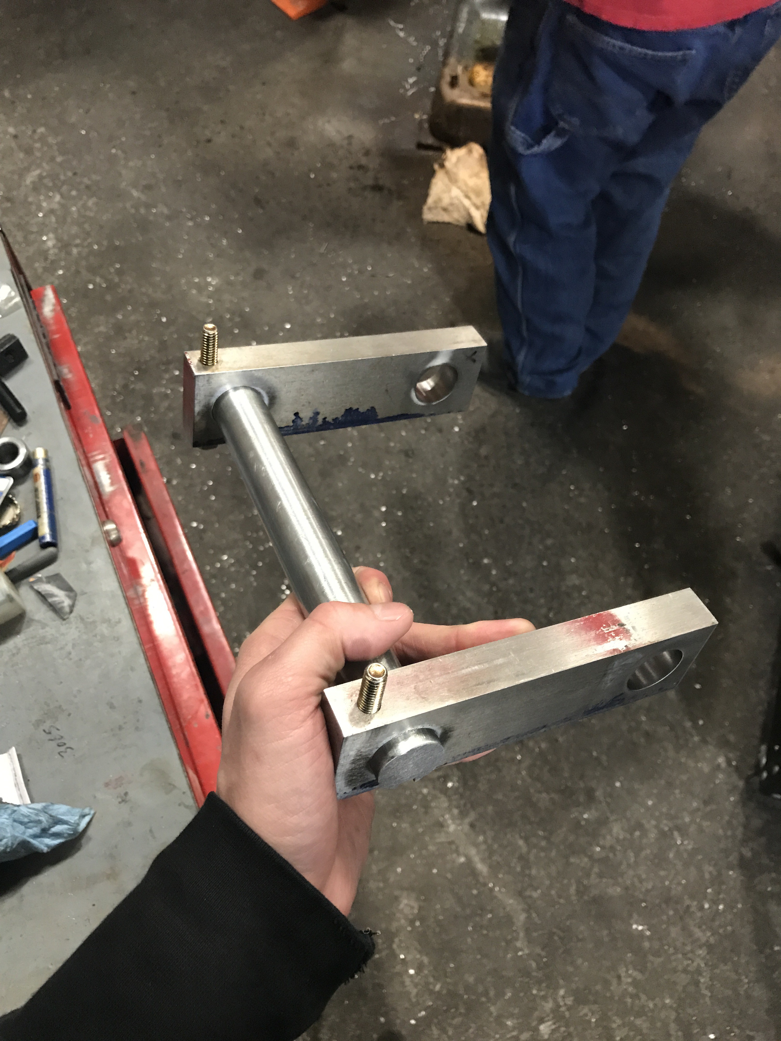
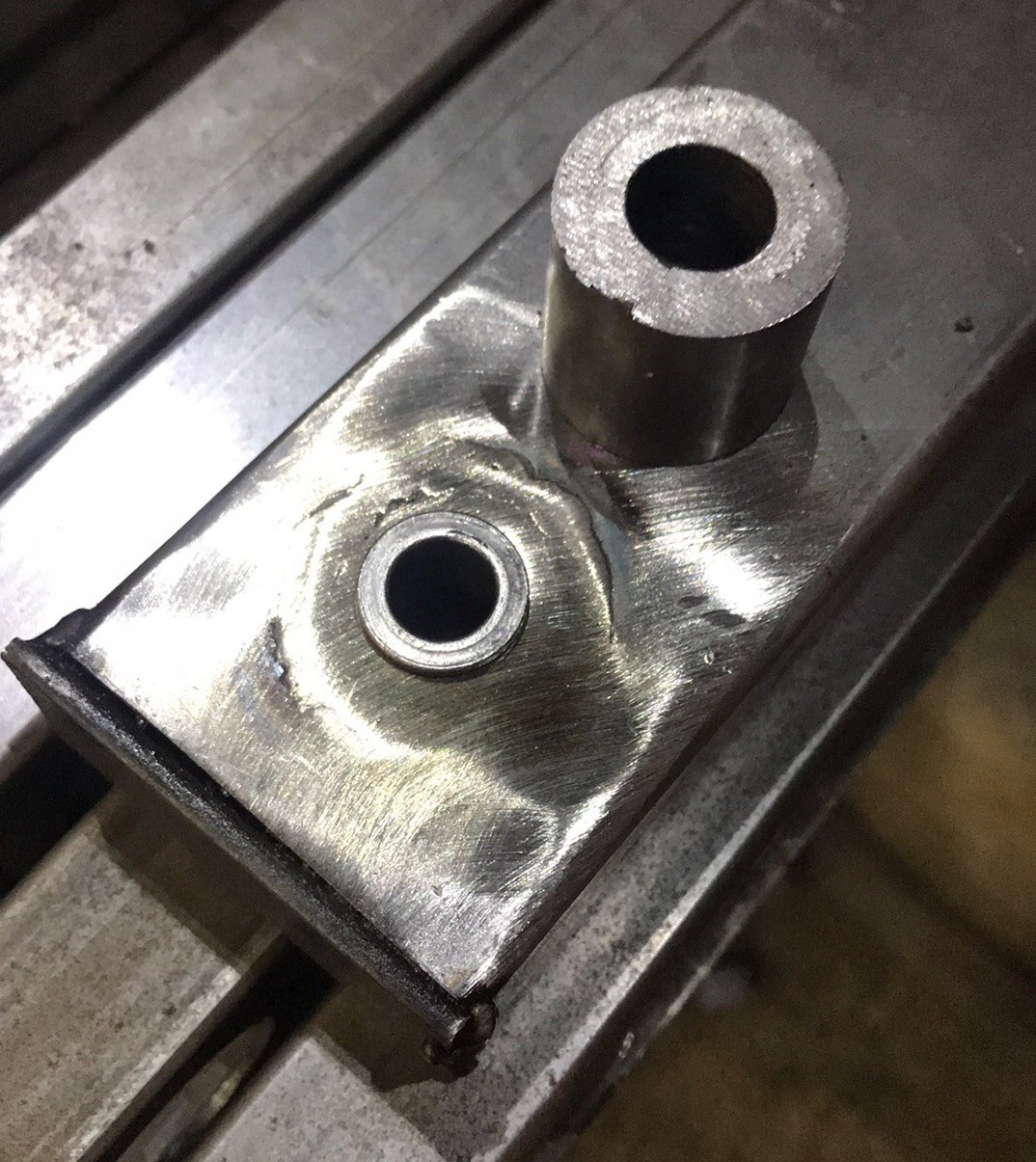
So, in order to achieve the lateral rigidity I referenced before, Shelly's individual leg components need to completely sheath the axel-bolts which hold the components together. I purchased round stock with a very thick sidewall and then used an annular hole bit to cut holes out of the leg components so I could weld the axle collars in. These collars were oversized just perfectly to grab onto the bronze Oilite bushings.
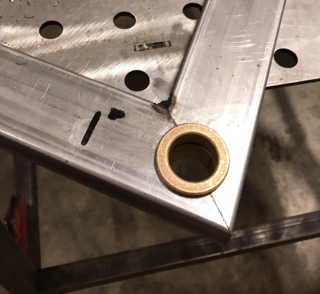
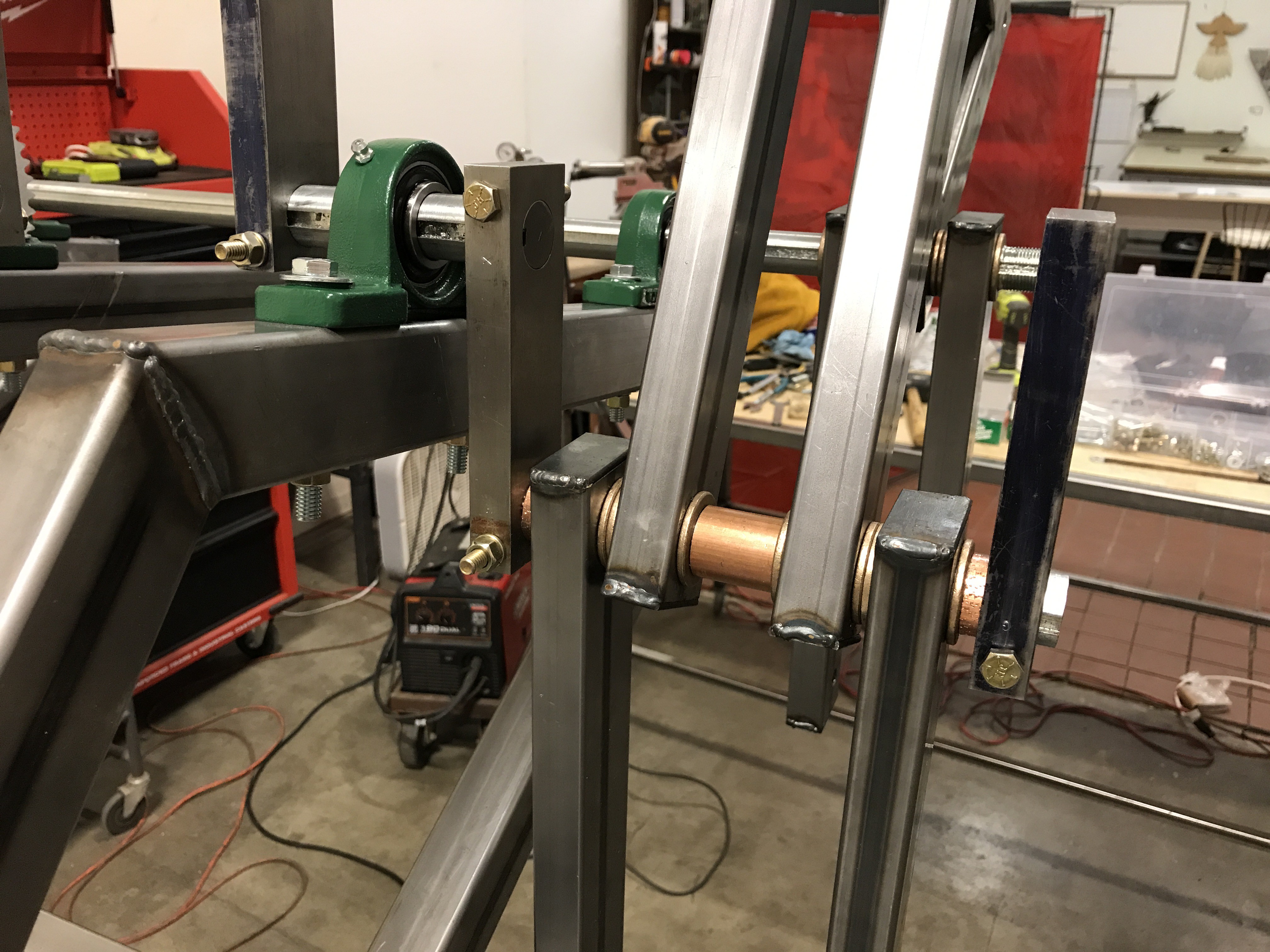
Portions of the legs connect to the 1" stainless steel crankshaft directly (instead of 3/shouldered bolts). These bushings connect directly to the bar-stock and are liable for the sidewall of the leg component to cut into the bronze bushing. I plan to replace those bushing as needed over time, since they are highly accessible and there are only 32 of them.
I ended up altering Shelly's Electronics many times. Here is the final design I settled on. Please review the parts list if you're curious about any specific component.
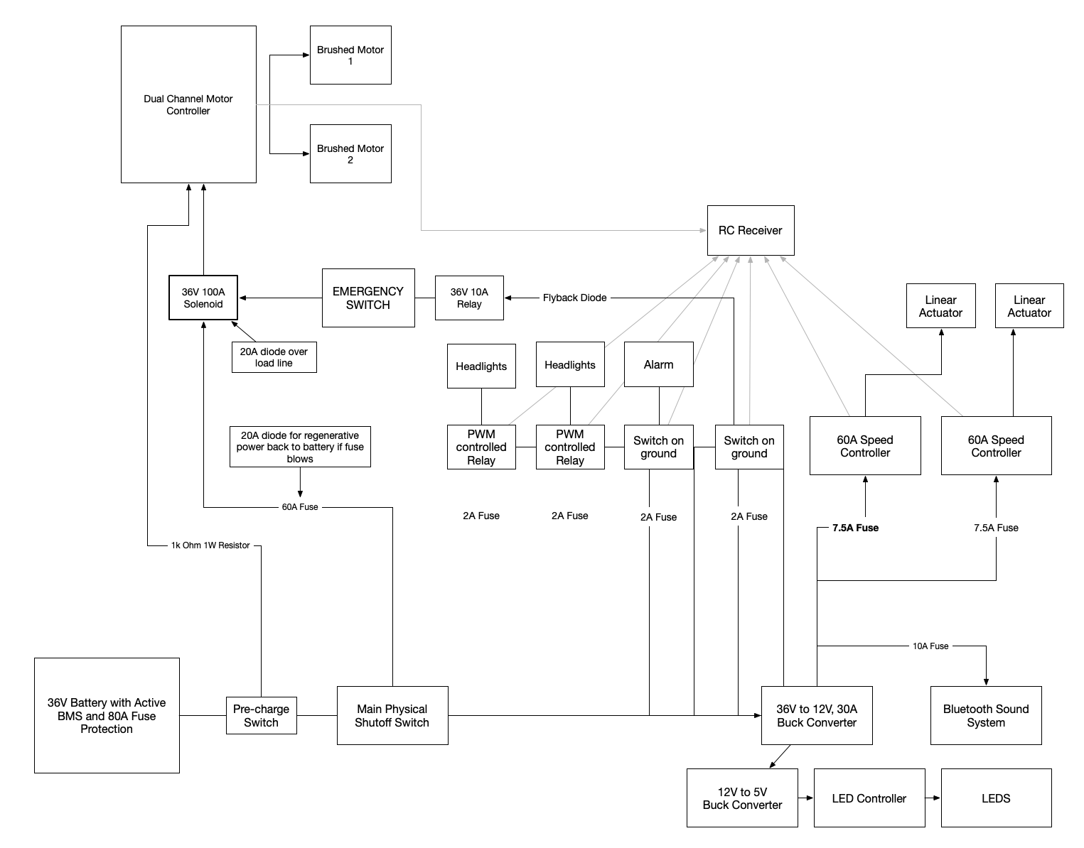
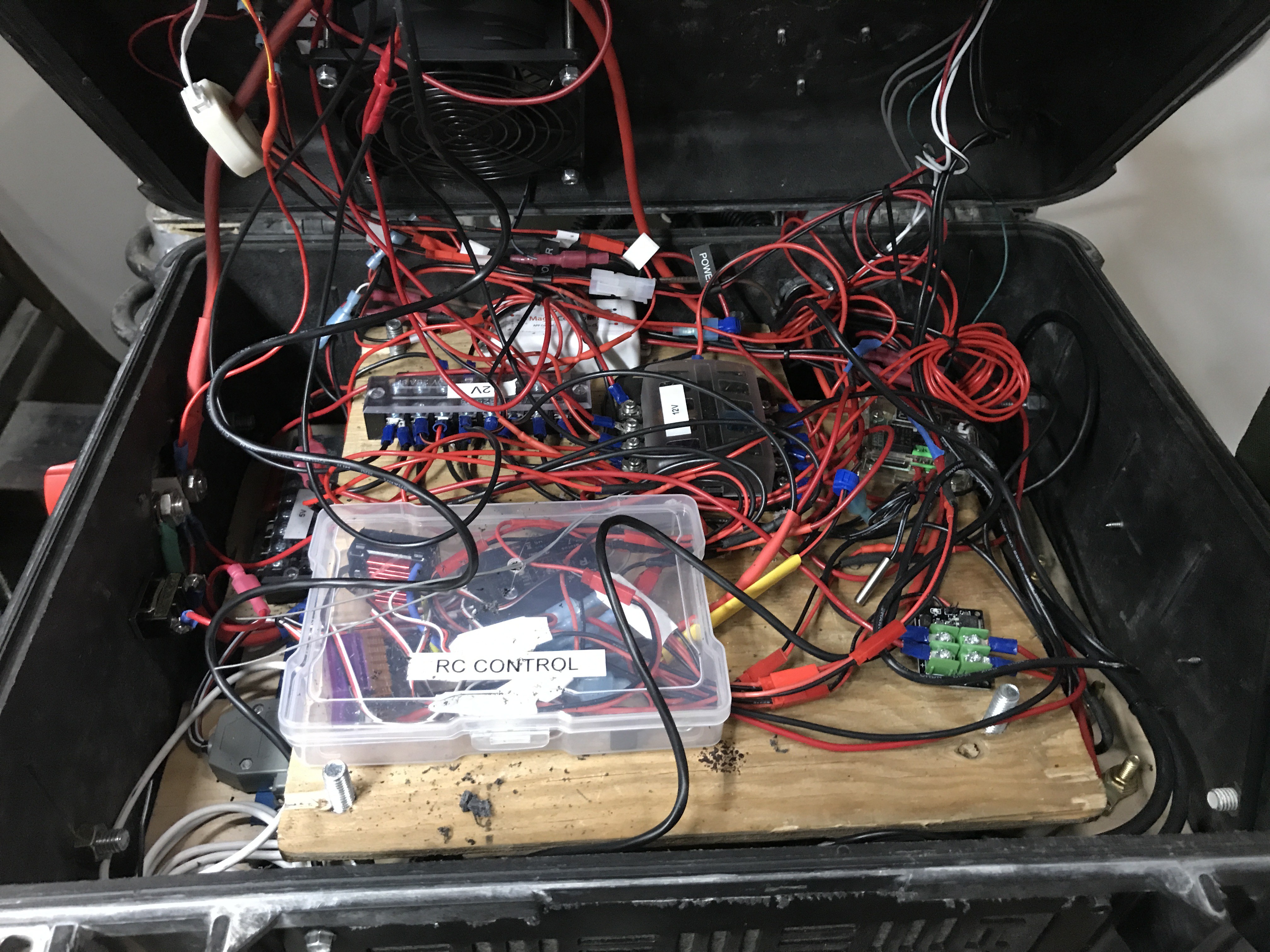
The final wiring should be ported to a PCB. The electronics box became a double-decker mess.
I'm glad I used a marine fuse box and bus-bars, as they helped me troubleshoot and protect components a few times during the build since the electronics were still very much in "prototype" phase and I learned a lot about underrated components.
Finally, a video showing her all together!