 Marian Keller
The first step of this project is to figure out how the instrument works in his native environment. Luckily, avionics tend to be documented really well. So I started out searching for an installation manual that tells how its usually wired up in the aircraft. This is the pinout diagram I found there:
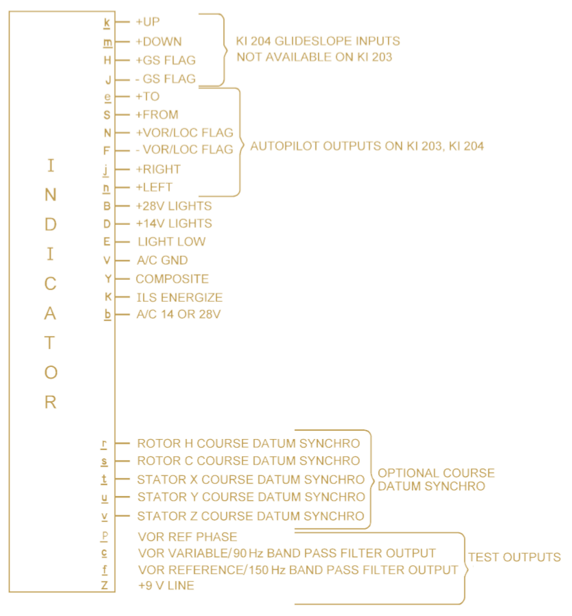
The Instrument is supplied by a voltage of 11 to 32 VDC between Pin b and v. This is to accommodate for both 14 V and 28 V power buses used in different aircraft.
The instrument lighting consists of two lamps in series between Pin B and E with a center-tap on Pin D. So depending on the system voltage, you can put +14 V on Pin D and ground the Pins B and E, or connect +28 V between Pin B and E.
Pin K is called ILS energize. Pulling it to ground will switch the instrument from accepting a VOR input signal to accepting a ILS input signal.
The actual control signal comes in from Pin Y - Composite. This signal comes out of the navigation receiver of the radio and is just a raw AM demodulated base band signal.
In the next post, I'll describe how this composite signal is formed by the real system, how it can be described mathematically, and how I first simulated it using MATLAB and my PC sound card.
Discussions
Become a Hackaday.io Member
Create an account to leave a comment. Already have an account? Log In.