I currently have all of the DPDT relays laid out on a board that handles the decoder logic for the 7 segment displays. I'm cheating here and converting BCD to 1 of 10, and then using diodes to drive the segments. I just don't have enough relays to do it properly. The multiplier section and divider section will work the same way. (Binary parallel multipliers are actually easier to make than binary parallel adders, but making it BCD makes it impractical. I could make a binary to BCD converter but it would require either 8 parallel BCD adders or would take way too long to do any math).
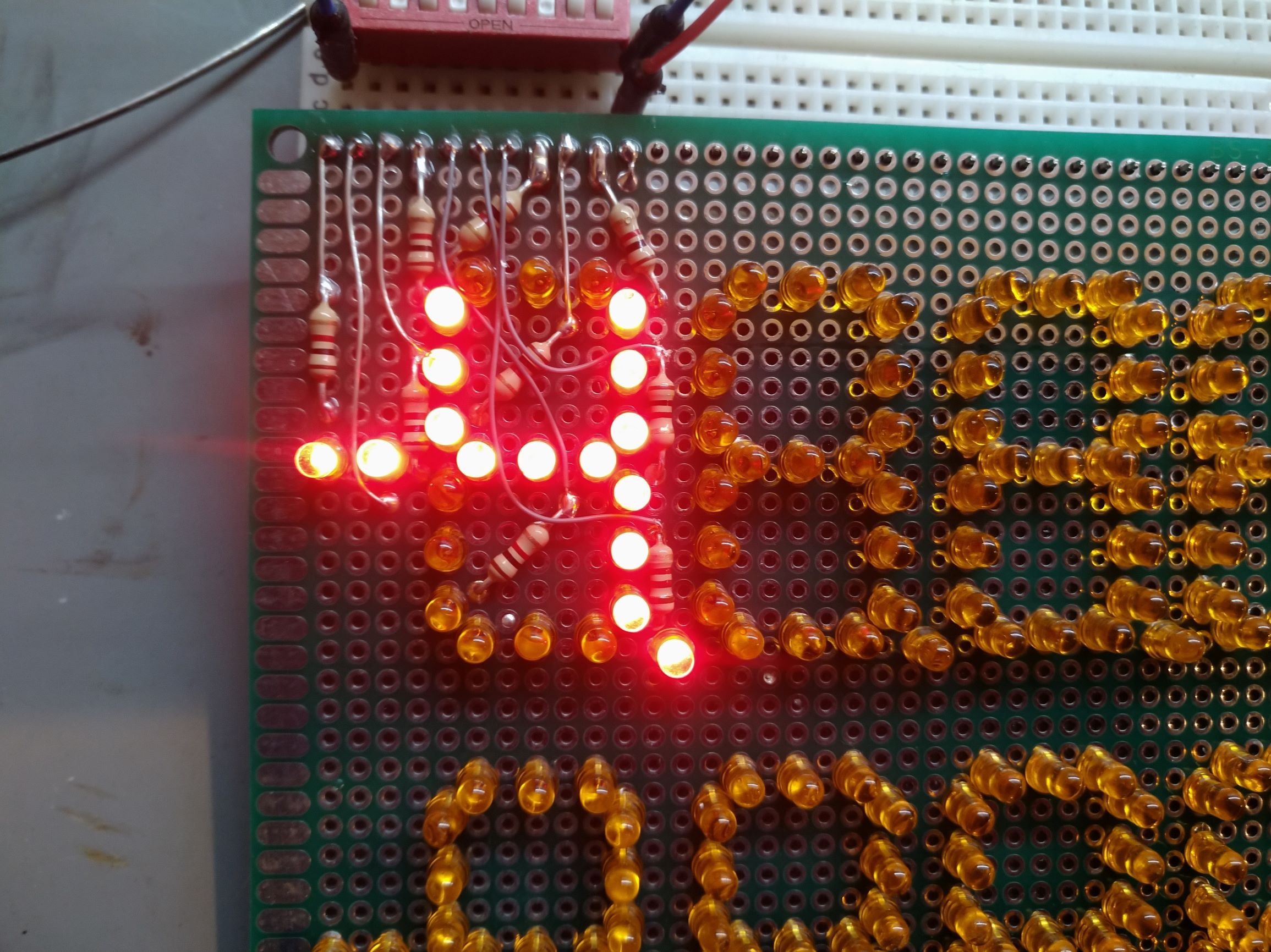
The SPDT relays are laid out on a board in an arrangement of three 8x4 registers. Two of the registers can shift right with the help of some 4PDT relays not yet on the board, and the remaining register can shift left and right, to accommodate user input arriving with the most significant digit first. I have 2 digits worth of registers wired as a test, as well as one digit of the display.
A long time ago I built a one digit BCD adder using 19 relays. I expect to add three digits together with 36. The multiplier and divider will share something like 38 relays and more diodes than I want to think about right now. Hopefully I don't run out of relays, but I know I will. I always do.
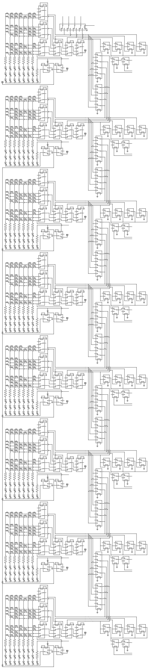
I have schematics but I make the schematic after I make that part of the circuit for some weird reason so they will be delayed. Here is a glimpse of it though.
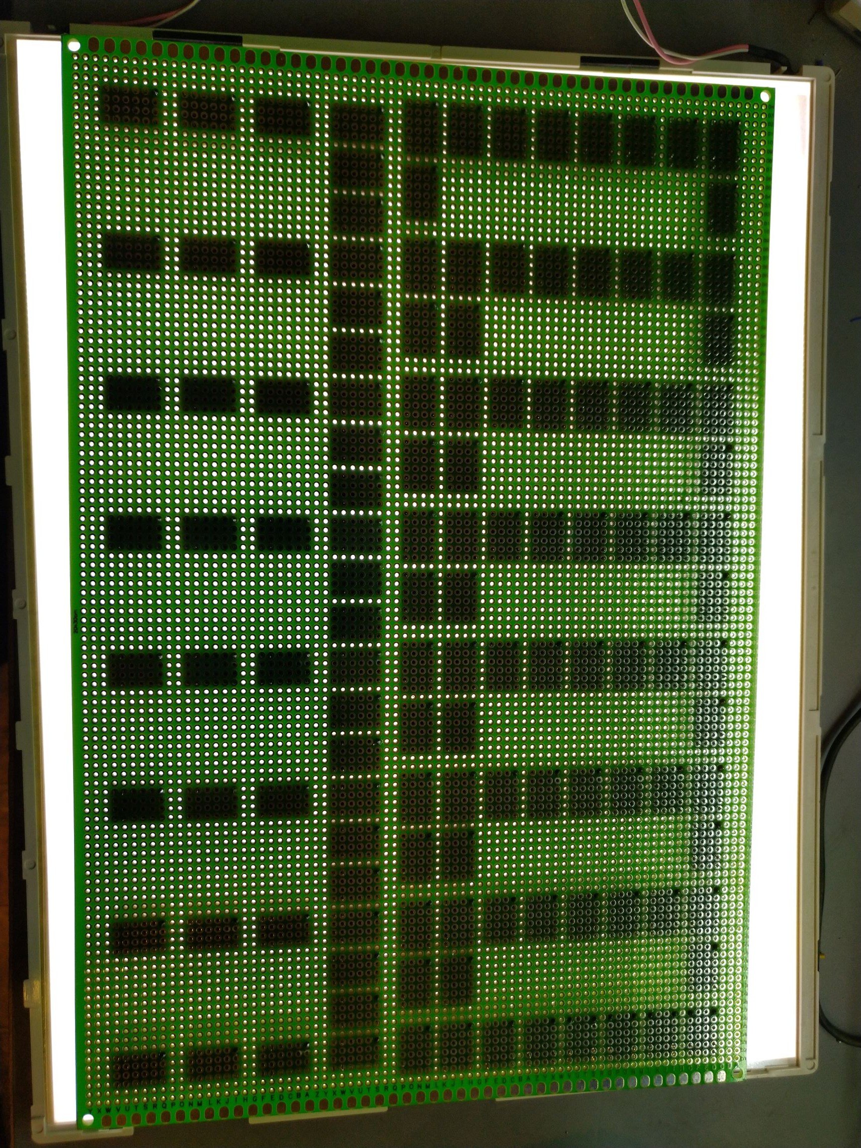
Using some sort of light table is really helpful to keep track of what all of the pins connect to. This is the backlight to an old monitor.
Discussions
Become a Hackaday.io Member
Create an account to leave a comment. Already have an account? Log In.