 Chris
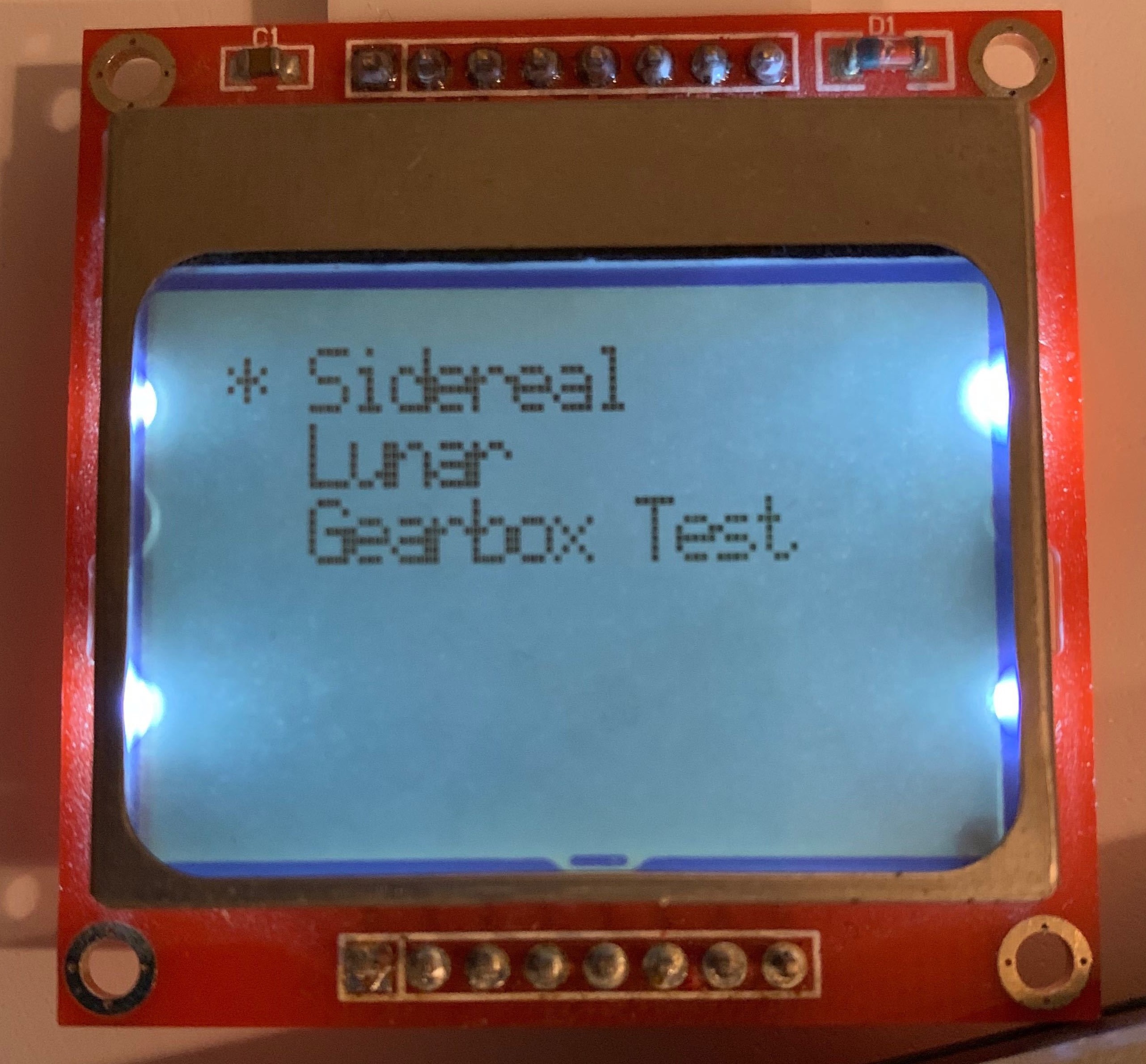
ChrisIn order to test the gearbox I decided to add a "Gearbox Test" speed to the firmware.
Driving at the normal rate could take a long time to make sure the last couple stages are moving at all. There's no reason they shouldn't be moving but that's the point of testing!
I encountered an unexpected problem though: driving the stepper any faster than a STEP pulse rate of 20KHz (which translates to roughly 80 RPM for a rate at the camera ball head of 0.008 RPM) and the stepper motor skips a lot of steps, enough so that it quickly stops moving altogether. The stepper driver's datasheet lists a minimum STEP pulse width of 1uS and we're well within that limit. What gives?
I believe the problem is that when it's being driven quickly there is not enough current is getting delivered to the stepper motor on each microstep. The A3967 driver looks for a variable resistance on REF to determine how much current to deliver to the stepper coils. This is by far the largest current consumer in the system and so the biggest dictator of potential battery life, which means that it is important to optimize for the lowest possible supply current while not sacrificing functionality. When I was prototyping a previous iteration of the project I used the EasyDriver's potentiometer to find the lowest supply current that would get the mount moving without skipping steps (~250mA) Problem is that I didn't recalculate the supply current in the current iteration, whoops!
There are two options:
- I can fiddle with the supply current by replacing R6 and R7 to change the voltage divider feeding REF but this board design can't deliver more than 3.3V at REF (should come out to about 400mA). If it turns out that more is needed I would have to do a board spin that divides down the 9V rail instead of the 3.3V rail.
- I can test each stage by running the stepper motor at the normal rate while the mount is disassembled and rebuild it, verifying that each successive stage does indeed rotate without "lurching".
I'm going with option 2. The last couple stages will indeed take a while to test but I'm not in any particular hurry, and not being in a hurry saves me money (no board spin) and effort (no redesign, no replacing the resistors).
Discussions
Become a Hackaday.io Member
Create an account to leave a comment. Already have an account? Log In.