Licenses: Software: GPLv3; Hardware: Creative commons BY-SA.
First outdoor test:
Frame design reasoning:
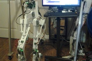
The frame dimensions - The first and easiest application (once I have autonomous navigation working) is to put UV lights on it to experiment as an alternative to fungicide on wheat. The current non-organic method is to blanket spray the crop every two weeks once it gets beyond a certain growth stage. This means the robot needs a decent ground clearance which is why it is currently so tall, and at the moment slightly unstable as you can see from the video. To fit down existing tramlines though it will need to be 2m wide so will be more stable.
The frame construction - For now the frames are built from handrail brackets and aluminium scaffold tube. Am loving this setup so far as it's so quick and easy to swap pieces out and reconfigure, just a few grub screws and the working height, width or length of the robot can be changed. While brackets are great for prototyping they may prove to be insufficient fixing once driving around a field. The other issue is that the tubes turn slightly when tightening the grub screws which makes wheel alignment very difficult. So for both these reasons I plan to drill through the front surface of the tube and use bolts instead of the grub screws to secure the tubes. This will also make it possible to properly align the wheels and will mean that the brackets can't slip over time.
The fixed wheel fork - Have left a decent sized area to mount ultrasound or LIDAR for obstacle detection. Have left space to put a mudguard on to stop it getting plastered if it becomes an issue.
The Steering Wheel - The photo with a 3rd wheel on the robot was the testing of my steering wheel. The steering motor passed the torque test but in the process the sprocket slipped on the motor shaft and bent it. I have a replacement shaft now but haven't resolved the poor fixing issue yet. The other issue is that this assembly is seriously heavy, around 50kg including the hub motor so do really need to rethink this design.
The eventual plan is to have 4 of these on the robot so can travel in any direction. This will mean can make the robot 2m by 6m wide, so that it can drive up and down the field in the 6m direction, but into the shed and along tracks in the 2m direction.
Specifications so far:
~80kg total weight
100 kg - Maximum total weight /wheel
10 mph - Top speed in theory - not daring to test it until less top heavy!
 Junglist


 Ted Huntington
 EK
EK
 Aaed Musa
 Roger
Roger
Nice work!