Close
0%
0%

WiFi to 433 MHz bridge

Toggle 433MHz sockets using network connected smartphone

Public Chat
Similar projects worth following
Before Christmas, I decided to buy remote controlled electric socket. It works well for Christmas tree, because when leaving home, we don't need to unplug Christmas tree lights manually.

I was lazy and sometimes forgot to take remote control, when going to bed.

Then I thought to build my WiFi to 433MHz bridge. This, in theory should allow me to control these sockets (and lights) via network-connected smartphone.

So... I did it!

Sniffing packets

For ability to replicate switch on-off packets, I've built 433 MHz sniffer on breadboard. This subproject involved ESP32 and XY-MK receiver module. Then, I've used ShowReceivedCode.ino example to retrieve unit address and ID. It took me a while to understand protocol that was used by my remote controlled sockets, but eventually I've ended up with working prototype.

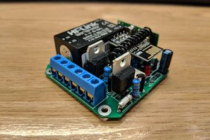
Printed Circuit Board

FS100A moudle was easy to use, but there was a problem to achieve small PCB size using this module. I've started to find an alternative. I have read a lot of various RF module's datasheets and hopefully ended with RFM110W-433S1. Theoretically I didn't know if it will work or not, but had a lot of hope.

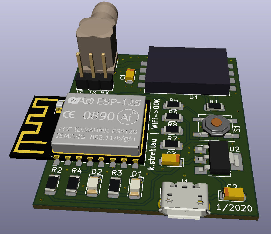
Simultaneously, just after ordering these modules on Aliexpres, I've started KiCad schematic and PCB project. I knew that I wanted to use ESP8266 and RFM110W. I've also placed two leds, first to indicate if we are in config mode, second to indicate RF transmission, like it's done on ethernet ports in your PC.

Worst part. Waiting.

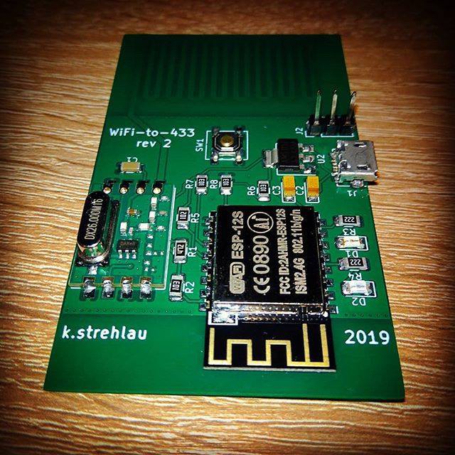
It took about three weeks from design finish to receive parcels containing RF modules from Aliexpress and fabricated PCBs from JLC-PCB. Eventually all of them arrived in excellent quality, well packed in anti-static bags.

Soldering

I'm not a soldering professional, so I had to go with "trial and error" method. Hardest part was to solder USB port, because I haven't done this before. However, thin soldering iron did the job. Everything has been soldered using solderpaste (with flux included). Every other small element has been soldered with hot air gun.
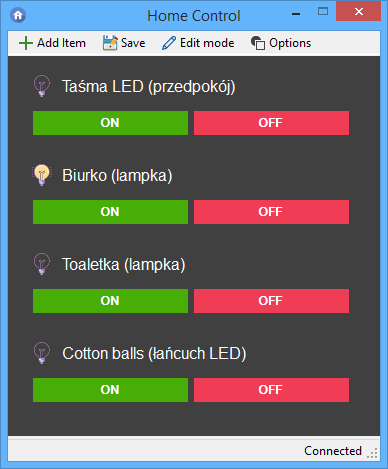
The software novel

I've started with Blynk library. It was a lot of mental pain for me. It is great example how to NOT create libs. Want to use Blynk in more than one C++ class? Forget about it! Without workarounds it is not possible. Anyway, I've spent two weeks due to frequent disconnections/reconnections to Blynk cloud server.

I was about to scream "I surrender", but I realized, how good MQTT is and quickly decided to drop Blynk.

MQTT was very good, but still it was reconnecting every few hours. After trial and error with manual etharp_requests and other crazy things and hacks, I tried to compile my code with LwIP 1.4 instead of 2.0. Simultaneously I've changed MQTT broker to cloudMQTT. 

These changes ended up with great reliability improvement.

  • 1 × ESP-12F / ESP8266 wifi capable system-on-chip
  • 1 × RFM110W radio transmitter module
  • 1 × Tact switch
  • 4 × 10 k Ohm 1206 SMD resistor
  • 2 × 220 Ohm 1206 SMD resistor

View all 11 components

  • New dipole antenna

    h4rdc0der11/16/2020 at 17:07 0 comments

    I've ordered 433 MHz dipole antenna - resolved problems with missing on/off signals. It's well-matched now, because for monopole antenna there is no good quality ground plane.

    Firmware has been rewritten, now is based on my IoT framework library.

    Feel free to use and contribute
    https://github.com/cziter15/ksIotFrameworkLib

  • New boards arrived and assembled

    h4rdc0der03/03/2020 at 18:22 0 comments

    I have assembled new boards. After testing I can say, they work as expected. My friend is designing 3d-printed enclosure. Looking pretty cool!

    Anyway I have discovered that my remote power outlets are designed really bad and I am unable to do anything with it.

  • Blynk back!

    h4rdc0der02/03/2020 at 18:51 0 comments

    Amazing news

    As I said before, I hate how Blynk Arduino library is written. Inspired by blynk-mqtt bridge python script shared at github i wrote my own application in C# to work more reliable. Why? Becaus I still love Blynk Android Application!

    Grab it and have fun

    This application has been shared on github as open source code. Grab it here and have fun!

  • New things!

    h4rdc0der02/02/2020 at 18:46 0 comments

    New year, new things! 

    I decided to completely rework this project with my recent knowledge.

    Previous revision had a lot bugs, for example antenna's impedance was not matched to feed. It matched only PA output of my radio module. I decided to replace pcb antenna with SMA connector, which allows user to match antenna on his own.

    PCB size has been reduced, all tracks have been moved onto top layer, more vias have been added - it all theoretically should improve device reliability.

    Now waiting for PCB fab to do their work :)

  • Revision 2

    h4rdc0der11/08/2019 at 16:23 0 comments

    I decided to make second revision of this project, with PCB trace antenna. I had to match impedance and length and this was skipped in first version. This module works a lot more reliable :)

  • PC controlled desk light

    h4rdc0der06/17/2019 at 19:00 0 comments

    New video from PC cotnrol app. It's fantastic, looks like my module can handle up to 100m distance!

  • PC Control app

    h4rdc0der04/25/2019 at 16:08 0 comments

    I wrote (using C#) small PC MQTT client app to easily turn on/off lights in my house using in-app buttons or Windows tray context menu. I have used M2Mqtt to handle MQTT protocol and Newtonsoft.Json to store user data (button definitions).

View all 7 project logs

Enjoy this project?

Share

Discussions

D Khazz wrote 11/27/2020 at 21:36 point

Have you shared a repo with your schematic and pcb files but I’m just missing it?

  Are you sure? yes | no

h4rdc0der wrote 12/28/2020 at 16:48 point

Not yet. Only software framework is shared.

  Are you sure? yes | no

stefan.schnitzer wrote 02/02/2020 at 19:13 point

Very neat and beautiful PCB!

I built something with similar functionality but with an Arduino and an ESP8266. https://hackaday.io/project/167904-diy-scada-wireless-remote-io

It's one of the Solutions you mention as "But why? Why do they use low spec microcontroller to tell ten times more powerful microcontroller what to do? Pure overengineering." But it's not over-engineering. I was just lazy :) 

  Are you sure? yes | no

h4rdc0der wrote 02/03/2020 at 17:40 point

Thanks! Greetings to JLCPCB :)

Well, when you are just lazy but still conscious, then its OK :)
The problem is, when people just copy idea without thinking.

This project uses Arduino too, but only as software base.

  Are you sure? yes | no

Elliot Williams wrote 06/21/2019 at 15:21 point

Beautiful and simple!  The realization that many of the "systems" out there are as hard to configure as writing it yourself would be is very familiar.

I run an open bridge, based on an ESP8266 plugged into a 433 transmitter, at home.  You just send a numeric code to the MQTT channel, and it spits it straight out to the radio.  Done and done, in something like 40 lines of code. 

(Your frontend looks nice!)

  Are you sure? yes | no

h4rdc0der wrote 06/21/2019 at 15:52 point

The problem is that many of these "systems" are just overengineered. Non-modular software architecture and also problems with PCB design even at logic level - a lot of people combine ESP8266 with Atmega and talk via AT Commands between them. But why? Why do they use low spec microcontroller to tell ten times more powerful microcontroller what to do? Pure overengineering. 

Why not just flash ESP with custom code that handles everything? :)

  Are you sure? yes | no

Similar Projects

Does this project spark your interest?

Become a member to follow this project and never miss any updates