 Patrick Graham
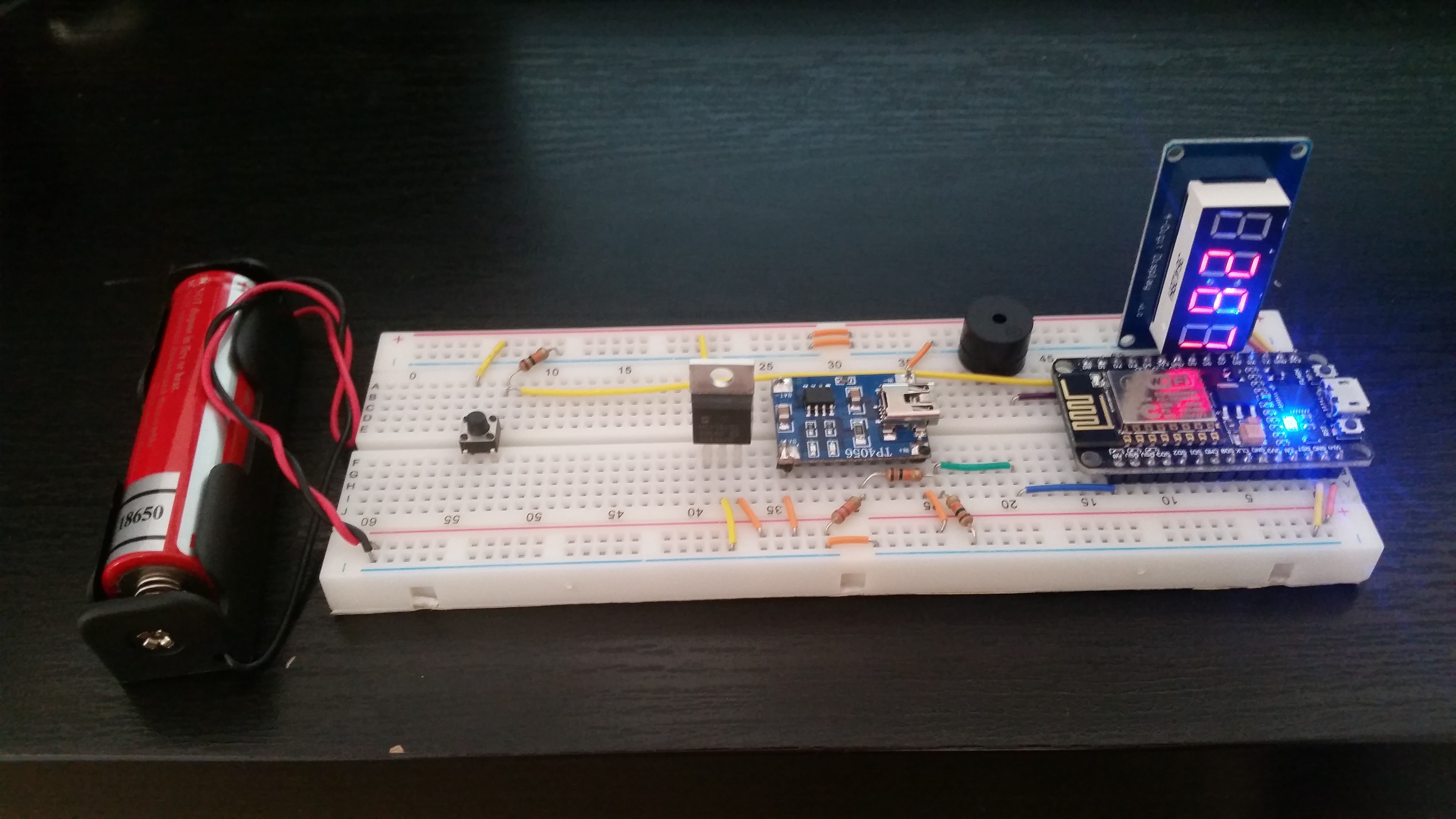
I've assembled the parts on a breadboard and written just enough code to test each component. I've also learned the very basics about how to create a rechargeable IoT device that reports it's battery status, though I still have a lot more to learn.
The battery is a 3.7V Li-Ion 18650, which when fully charged will output 4.2V. I decided to add an MCP1825S, an LDO regulator, which will regulate the power coming from the battery to a constant 3.3V because I don't know what to expect if I don't. Probably blue smoke. I'll be using the one analog input on the ESP8266 to measure the charge left on the battery.
The analog input seems to be reading a 10 bit value from 0V-3.3V, but I read that the pin is only rated to measure accurately between .1V and 1V. To bring the reading into that range I added a voltage divider so the maximum charge of 4.2V on the battery will read as 1V. The voltage divider consists of a 22kΩ and 10kΩ resistors in series coming from the battery to a junction, which then connects to the analog pin and to another 10kΩ resistor that goes to ground.
Once I got this working I tested it out by flashing the ESP8266 with an arduino sketch that would measure the reading and display it to the TM1637, the 4 bit 7 segment clock display. I also tested out connecting a button and a buzzer. I hadn't even seen this documented elsewhere, but variables for the NodeMCU pins were already mapped. This must be part of the board definition. I found this out when I went to create variables for mapping each pin index to what is written on the NodeMCU. So instead of using the number 16 to refer to the GPIO16 pin when calling digitalWrite, for instance, I can just say D1. I talked to a few other people who have been deploying arduino sketches to the NodeMCU and they didn't realize this either. I still haven't tested this out for the non-GPIO pins, but it seems like some of the most popular tutorials skip this detail or maybe its just a more recent improvement.
Now that I have the basic setup complete I'm going to try creating some schematics for it using Fritzing. I'm having a little trouble figuring out how to create new parts for Fritzing, but it seems like most of the work is done outside of Fritzing using your vector editor of choice. I'll try to have the sketches ready for my next post.
Discussions
Become a Hackaday.io Member
Create an account to leave a comment. Already have an account? Log In.