 Alastair Hewitt
Audio testing is now complete. This includes both hardware updates and the software to generate the sound. Since the sound system is finalized this would be a good point to review all the gory details.
Hardware
To keep the hardware minimal, no registers are dedicated to the audio. Instead time is borrowed from the GPU's glyph (G) register during the horizontal blanking period. The GPU address registers (H and V) are left in tristate during blanking and pulled high to generate the address 0x0FFFF. This is the top byte of the zero page and reserved to store the next audio sample as a 7-bit signed number. The blanking period also switches to the ALU instead of the font ROM with a special audio function at 0x3FFXX. This function remove the sign bit to create a DC-biased audio level and reverses the bits since due to PCB layout constraints the MSB of the audio DAC connects to the LSB of the register.
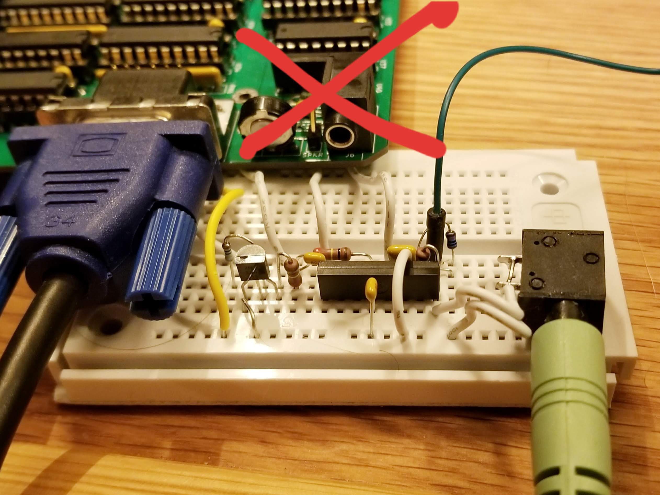
The audio DAC gets the full glyph signal during the active video period and the initial design attempted to use a sample and hold circuit to sample just the audio when blanking. This didn't do a good job of isolating the video signal and led to a lot of noise issues. The circuit was redesigned to the following:
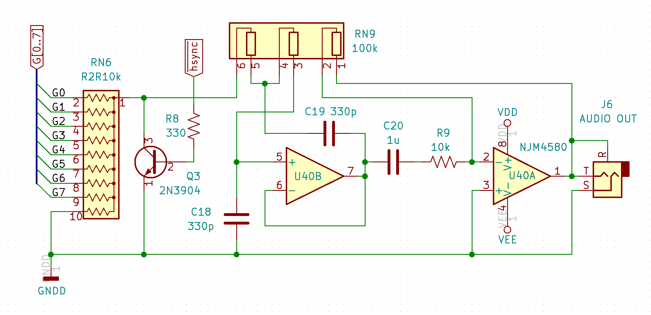
The new design uses the H-sync signal (blue trace below) to mute the DAC during the active period and then allow the audio signal (yellow trace below) to recover during the blanking. This presents pure PCM pulses to the audio filter stage rather than the typical step function. This isn't a problem since they both contain the same frequency domain information. The power level is a lot lower though, so a 20dB inverting amplifier is needed to bring the level up to the -10dBv line level.

Prior to the amplifier are two filters: A second-order Sallen-Key low-pass filter followed by a passive high-pass filter. The high-pass cuts frequencies below 16Hz and the low-pass above 4.8kHz. This is the Nyquist corner frequency when generating audio at the standard 9.6kHz virtual process rate. The frequency response is shown below:

Software
The same method used by the Gigatron was shamelessly copied to generate the audio waveform here: A lookup table is used to map each note to a 16-bit value that is then added to a 16-bit counter register. The addition is done at a fixed sample rate such that the register counts to 65,536 at the frequency of the note being played. The upper 8 bits of this counter are then used to index another lookup table that contains a sample of a waveform. Multiple voices are generated by using additional 16-bit counters for different notes and adding the result of waveform lookups together.
Two functions are included in the ALU to lookup the note by the MIDI value and return the high and low byte to use for the 16-bit counter register. The table goes from 0 to 127 for use with the non 60Hz VGA video mode, where full 88-key piano keyboard goes from 21 to 108. For 60Hz VGA the sample frequency is slightly different, so the table is duplicated for this frequency between 128 and 255. In both cases the entire 88-key piano frequency range can be played.
Voices
The Gigatron is able to compute one voice per line during the horizontal sync period. The Novasaur requires up to 48 compute cycles to calculate each voice, which is longer than the entire virtual machine cycle containing the horizontal sync. The audio has to therefore consume additional machine cycles and is treated as an optional feature with the number of voices made configurable.
The audio is handled by a non-blocking thread scheduled at the end of the first line in the virtual process cycle. At least 2 virtual machine cycles are required if the audio is enabled and this can be extended by an additional cycle per voice up to a total of 4 cycles. The first two cycles provides the first melodic voice and an additional non-melodic voice that would typically generate a random noise signal. Each additional cycle adds a voice for up to 3 melodic voices in the VGA and SVGA video modes, or 2 voices in the XGA mode.
The non-melodic voice uses the process line counter of the video display instead of a dedicated 16-bit counter register used to control the frequency. The result is a cycle frequency that matches the 60 or 75Hz frame rate of the video. The noise sample would contain all frequency harmonics across the audio range, but this repeats every frame for a significant 60 or 75Hz harmonic. This can be mitigated by using two patterns that alternate based on the sign of the audio signal at the end of the frame. This still causes issues if only that noise signal is being generated, but mixing one or more melodic voice will modulate the selection between the two noise patterns.
All the voices are calculated on the same line. The result of each voice calculation is a signed number that is summed to determine the final value of the audio sample. This sample is then output on every line until the thread runs again on the next process cycle. Even though the resulting PCM pulse is output at the horizontal line frequency the value only changes at the process frequency shown below:
| Video Mode | Horizontal Frequency | Pulses per Cycle | Cycle Frequency | Nyqust Frequency |
|---|---|---|---|---|
| VGA 60 | 31.5kHz | 3 | 10.5kHz | 5.25kHz |
| VGA 75/SVGA | 38.4kHz | 4 | 9.6kHz | 4.8kHz |
| XGA | 48kHz | 5 | 9.6kHz | 4.8kHz |
Waveforms
There are three waveforms available for the melodic voices: sine, square, or sawtooth. These waveforms are stored in a wave table consisting of 16 entries. The sine wave takes up one entry and the noise patterns take up two. This leaves 13 entires for the other two waveforms, with 6 entries for the square wave and 7 for the sawtooth. But why so many?
The square and sawtooth waveforms are very rich in harmonics: The sawtooth consists of every harmonic with a second harmonic at 1/2 the amplitude, the third at 1/3, the fourth at 1/4, etc. The square wave is similar, but contains only the odd harmonics. The issue arrises when you consider what happens to these harmonics with the relatively low Nyquist corner frequency of 4.8kHz. As an example, if one of these waveforms is generated at 1kHz then there will be alias distortion at the 5th harmonic and above. The 5th harmonic is only -14bB below the fundamental, the 6th is -15.5dB, the 7th is -17dB, etc. These are still quite significant amplitudes and quite noticeable on the Gigatron with a Nyquist corner frequency of only 3.9kHz.
The solution is to band limit the waveforms. Any note below 2.4kHz will not be able to reproduce any harmonics, so only the sine wave would be selected at these frequencies. Below 2.4kHz the harmonics can be added one at a time to produce a progressively richer band-limited version of each waveform. The diagram below shows the actual wavetable data for the sawtooth (in red) and square (in blue) waveforms. The first example shows two cycles of the 2nd and 3rd harmonic versions, the next is up to the 7th and 8th harmonics, and the final example is the highest harmonic version in the table with up to the 13th and 14th harmonics:
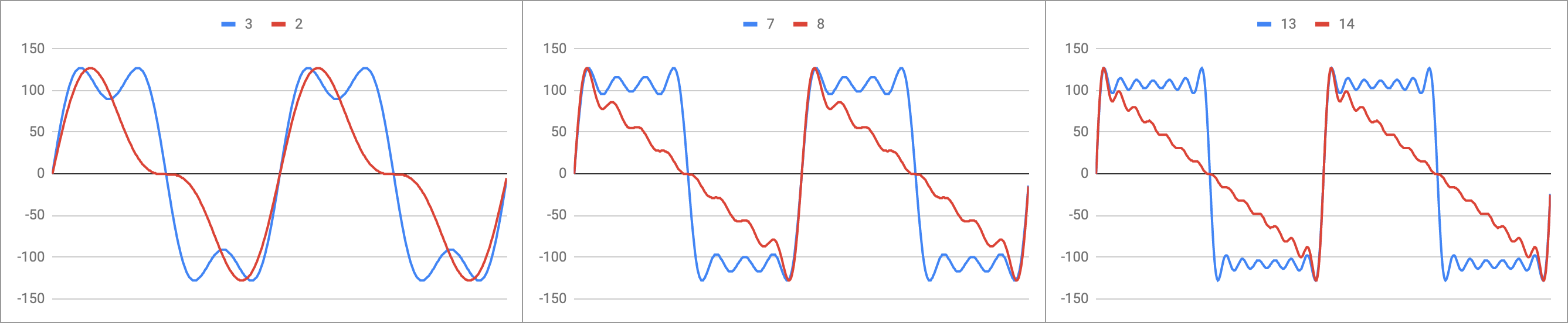
The next table shows the makeup of the wave table. The first column is for entry 0 and 1, where entry 0 is the fundamental (sine wave) and entry 1 is the fundamental plus the -6dB second harmonic (red line in left panel above). The next column is for entry 2 and 3, where entry 2 is the fundamental plus the -9dB third harmonic (blue line in left panel above). The last column are the two noise patterns. Each row progressively adds the harmonics, where the first row contains the sine wave and odd harmonics (square waves) and the second row contains all harmonics (sawtooth waves).
| 0,1 | 2,3 | 4,5 | 6,7 | 8,9 | 10,11 | 12,13 | 14,15 | |
|---|---|---|---|---|---|---|---|---|
| Square | 1 | +3 | +5 | +7 | +9 | +11 | +13 | noise0 |
| Sawtooth | +2 | +4 | +6 | +8 | +10 | +12 | +14 | noise1 |
An additional ALU function is used to find the table entry given the note where the highest harmonic will be below the Nyquist corner frequency and avoid aliasing. The least significant bit can be set to 0 to select the square wave, or 1 to select the sawtooth. This function is not needed to select the sine wave since you would simply select entry zero regardless of the note's frequency (Note: no entries exist for frequencies above the Nyquist corner frequency).
Attenuation
The waveforms are stored in the lower portion of the WAV ALU binary operation. This operation can be used in the single-cycle context and will return the value of the waveform as a 7-bit signed integer (-128 to +127). The WAV operation is a two-cycle operation however, where the second part of the function contains an attenuator to reduces the amplitude of the waveform during the second cycle.
The lowest attenuation is 12dB, or 1/4 of the sample value. The waveform has to be divided by at least 4 since up to 4 waveforms could be summed to create the final audio sample. This lowest attenuation has a value of 15 and then the amount of attenuation is increased by 1.5dB for each step going down to 1 for an attenuation of 33dB. A value of 0 represents full attenuation and the sample is muted to always return zero.
ADSR
Controlling the attenuation is useful for controlling the balance of each voice, but its primary goal is to control the envelope of the audio waveform. This is achieved by adding a set of envelope controls to each voice for the attack, decay, sustain, and release of the amplitude. The sustain is also used to gate the voice, so setting the sustain to a level above zero will cause the voice to attack to maximum volume and then decay to that sustain level. The sustain can then be dropped to zero to cause the voice to release to the muted state.
The resource consumption for the envelope control is relatively low: If the audio is enabled then each voice is updated sequentially at the end of the video frame with all voices updated at a rate of 15 times per second. The update involves increasing or decreasing the attenuation from 1 to 15 steps at a time. The fastest change would be 15 steps in 66ms, so turning the audio completely on and then completely off in 133ms (kind of slow). The slowest change would be 1 step per 66ms, so turning the audio completely on or off over a 1 second period.
The keyboard scan is also controlled at the end of the frame, so for 60Hz frame rates there are only 3 slots to control the envelope. In this case the third melodic voice would not get ADSR control, but can still be controlled manually if needed. Only the 75Hz video mode would provide all 4 voices with ADSR.
| Video Mode | Max Melodic Voices | Max Voices w/Noise | ADSR Voices |
|---|---|---|---|
| VGA 60 | 3 | 4 | 3 |
| VGA 75 | 3 | 4 | 4 |
| SVGA | 3 | 4 | 3 |
| XGA | 2 | 3 | 3 |
The algorithm utilizes an indirect addressing method to store a reference in the delta register. This would start by pointing to the attack register, which in turn would store the number of steps to add per 66ms each cycle. This positive number is added to the current level of the voice and checked to see if it has overflowed. If it has overflowed then the volume is set to the maximum and the delta is changed to reference the decay register. The decay is a negative number so the volume will start to decrease on the next cycles. The same overflow check is done for the zero crossing, but also a checked against the sustain level. If either is met then the level is set to the sustain and the the delta is set to zero. This indicates that there is no indirection for the delta and just to check if the sustain level has changed.
To gate off the voice off, the sustain level is dropped. This will cause the delta to be updated to reference the release register, which like the decay also contains a negative value. This results in the level dropping to the sustain level again, which would typically be zero. To restart the cycle the sustain level is increased triggering an update to the delta to reference the attack register again.
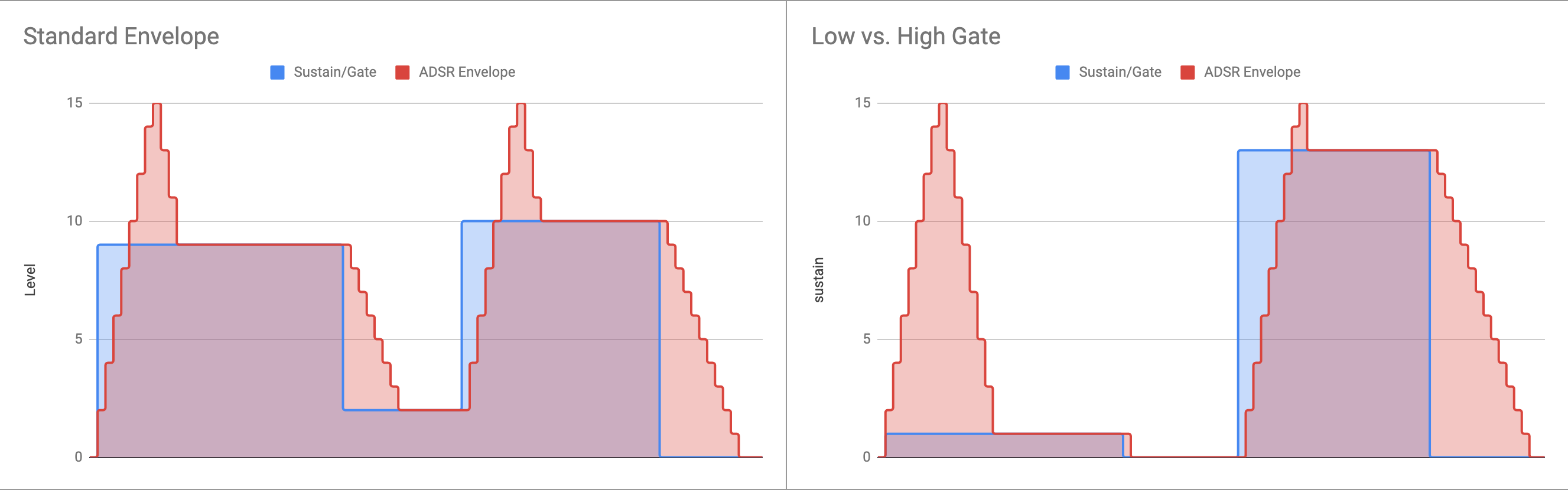
The examples below shows the effect of changing the sustain level and the resulting envelopes. The left example shows the cycle without dropping to zero between two notes. On the right is a low gate used to cause a short note and a high gate to cause a longer note.
One final feature is the ability to control the value of the wave harmonics using the envelope. The deltas are stored as 7-bit numbers where the lower 3 bits would normally be left as zeros. If they are not zero then the value of the wave table entry will be updated along with the amplitude. This acts like a voltage-controlled filter being controlled by the envelope and adjusts the harmonic content of the wave to add more texture to the note. The attack/decay deltas have to be symmetrical though. If the wave table doesn't arrive back at the starting point then it will drift over the noise entry and cause a nasty mess!
Discussions
Become a Hackaday.io Member
Create an account to leave a comment. Already have an account? Log In.