It's been a while since last update. There was a hugh amount of soldering that needed to be done. When I did the first power test nothing happened. I could measure voltage but nothing was on. I reviewed the wiring, that was correct. So I went back to my test LED matrix, 15x20, tested with the Arduino that worked ( I'm using the StandTest in the NeoPixel library to test with). I took that exact code to the Giant LED and it worked, only lighting up 300 LEDs. I realized that the Arduino could not handle 2100 LEDs. I switched to Mega and I was able light up all the LEDs.
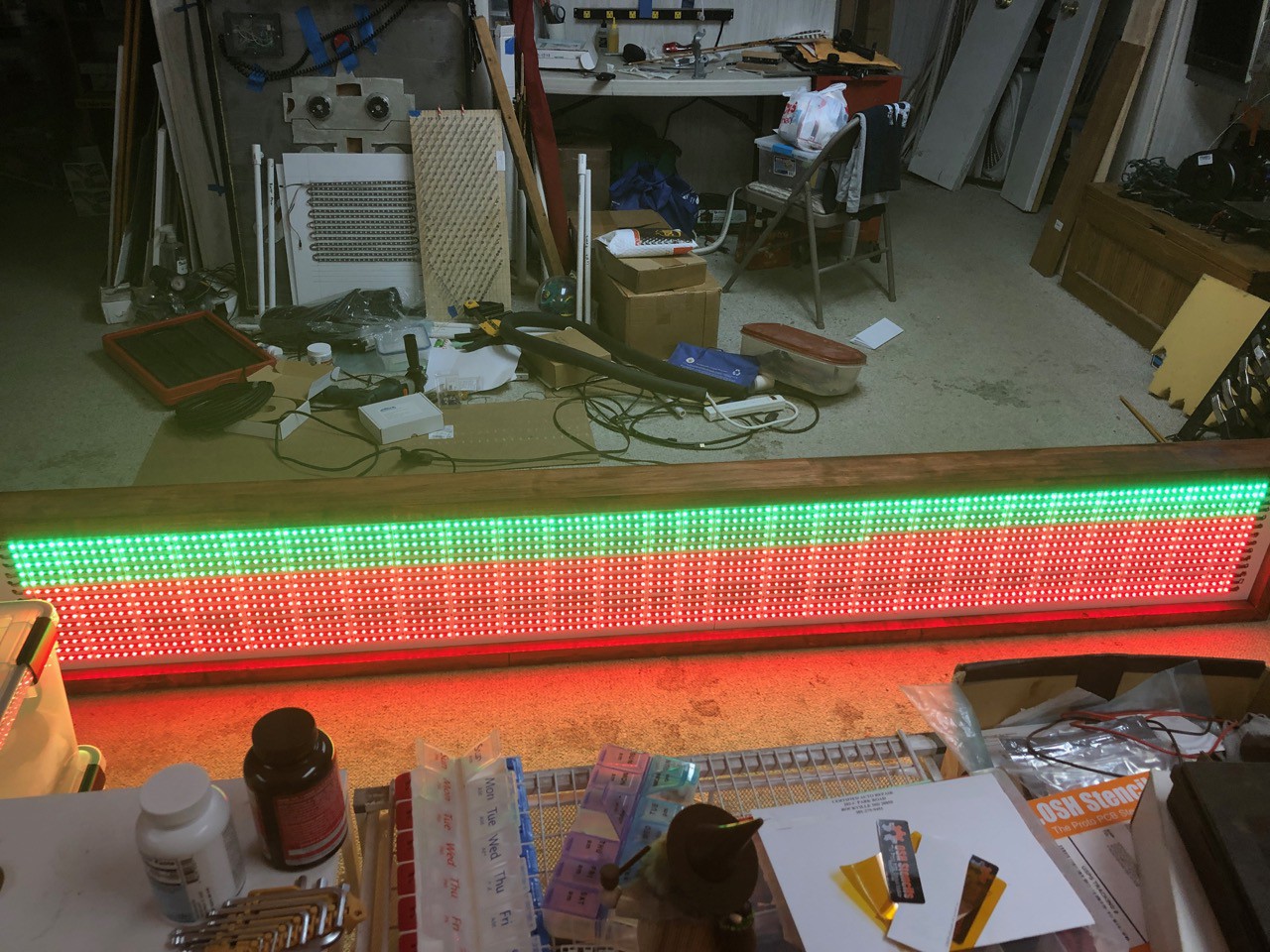
Picture of it working. At this point I was testing to make sure everything was working and look for dimming. Happily everything was working correctly.
For this test I was running off two power supplies.
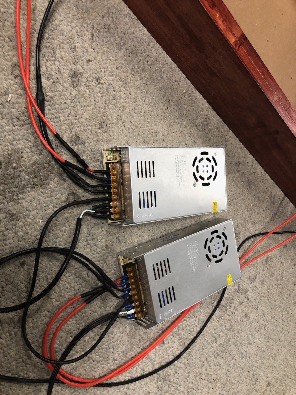
I was very very careful with this setup. I've had some bad experiences doing similar setups in the past. They share a common ground, if you look closely at the picture you can see it. Also, all the grounds for the LEDs are connected. I was careful to make sure each positive circuit is isolated from each other. I did some measurements on Wattage, and was happy to see that is was quite a bit lower than I expected. I could probably run everything on one power supply but it would be close to it's max load, 300W. I am very concerned with over heating, since the display will be running outside, mostly in a 4H Rabbit Barn. I'm going to keep the two power supply configuration, I kept the display on for about 45min and at the end checked the power supplies to see how hot they where, they where not hot at all.
Now some detail on the Hugh amount of soldering. I made a mistake that resulted in have to redo a large amount of the soldering. There is also a nice soldering patch that I'm very happy with.
Solder Patch "Challenge see if you can see it in this picture, I will explain it below"
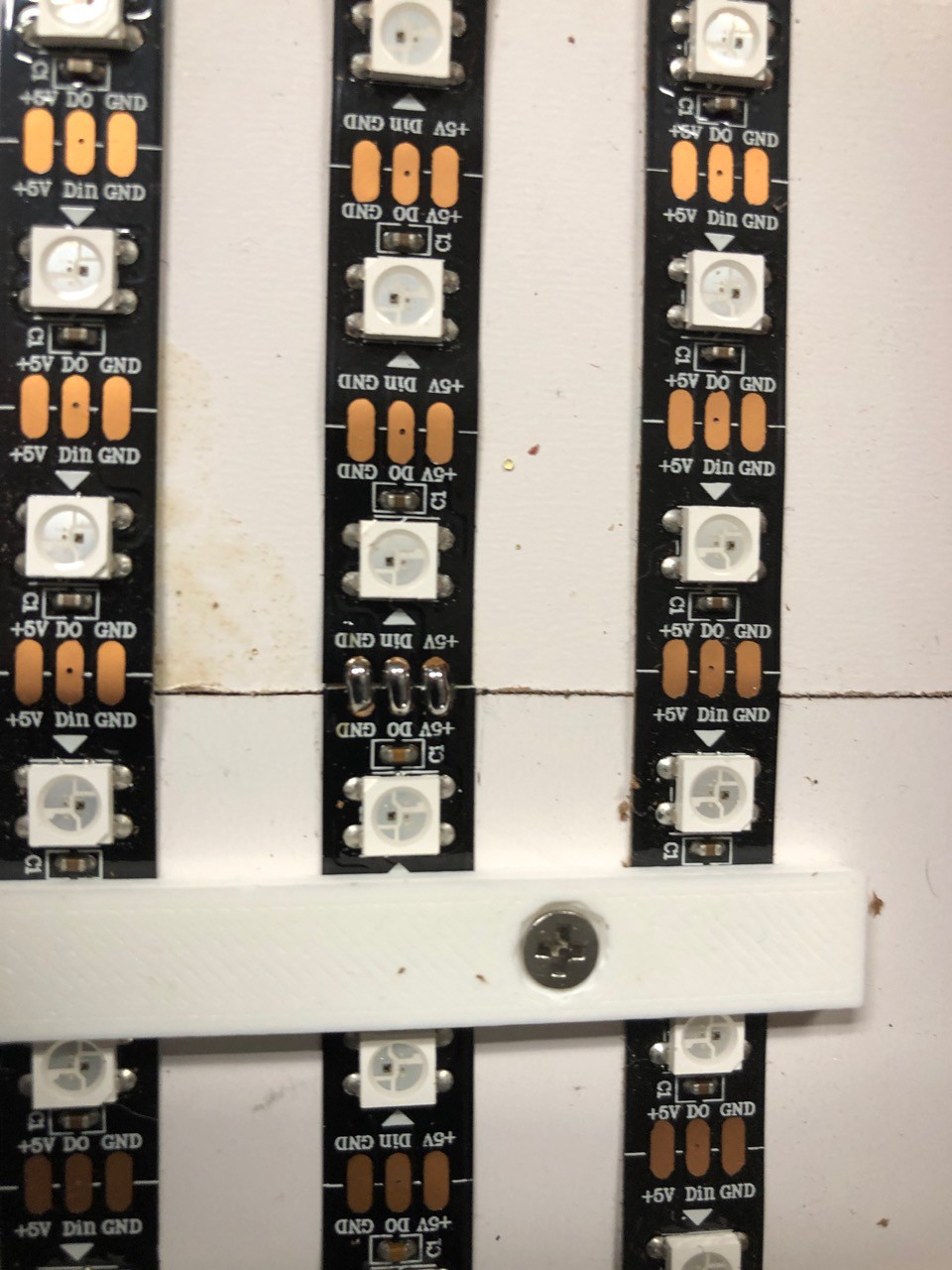
When the 4H kids where cutting the LED strips in half, they needed to cut on the line going through the solder pads. In one case this was not done very well, it resulted in a very very small pad to solder wires onto. Each strip of LEDs is 8ft 2in long, about $20 worth of LEDs so I do not want to just through a strip away. I decided to cut out the pad strip back to one of the 3D mounting brackets and then solder a short LED strip (6 LEDs long). This worked out very very well. Now I have a technique to replace part of an existing LED strip.
LED wiring
I wanted to route the wires to the back. This would make the front much cleaner. Also, I need the diffuser needs to sit directly on top of the 3D LED mounting strips.
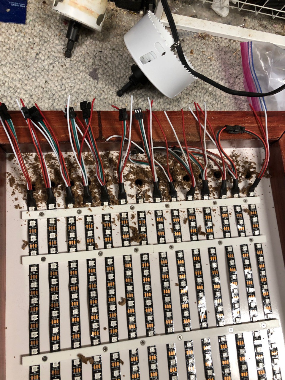
A bit of a mess at this point.
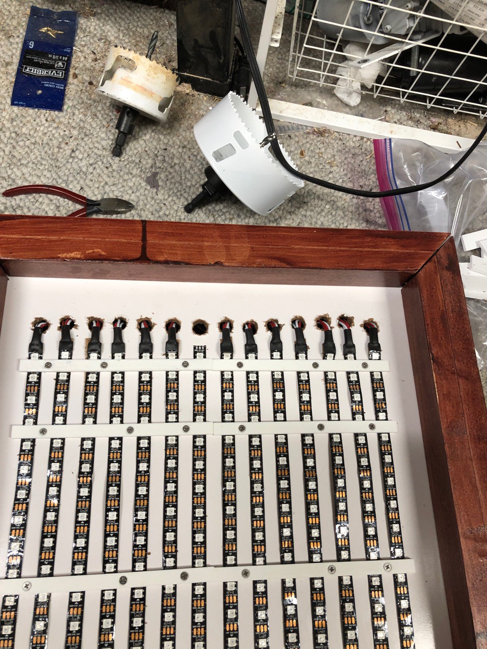
Nice a clean on the front. One draw back of doing this is that everything is backwards when you are soldering. I had finished all the soldering, but had this feeling that something was not right. So before I put power to anything. I went through and went through everything, that's when I realized I had worked up everything wrong.
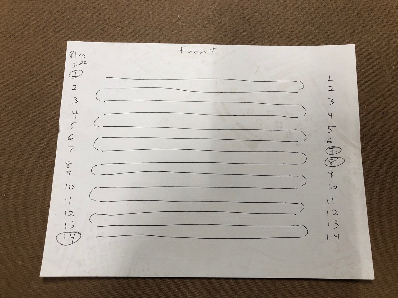
This is a very basic wiring diagram. We are connecting the LEDs in a Z pattern. The line between 1 - 2 and 2 - 3 are showing how the data line connects. You will notice that 1, 7, 8 and 14 are circled this is where 5V power is coming in. 1 - 7 and 8 - 14 are each on a dedicated power supply. This was the mistake I made not taking into account that since I was working on the back side that I need to reverse my diagram.
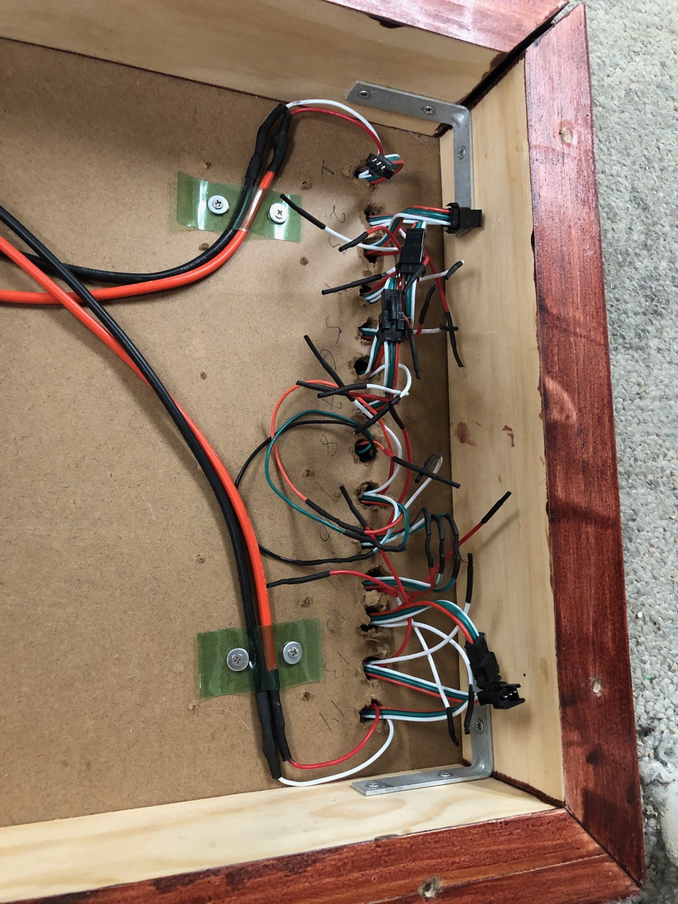
Looking nice and clean. Note on the other side I have a strip of brass that I use as a ground bus. Also, see the green wire tie downs. I used a plastic bottle for these.
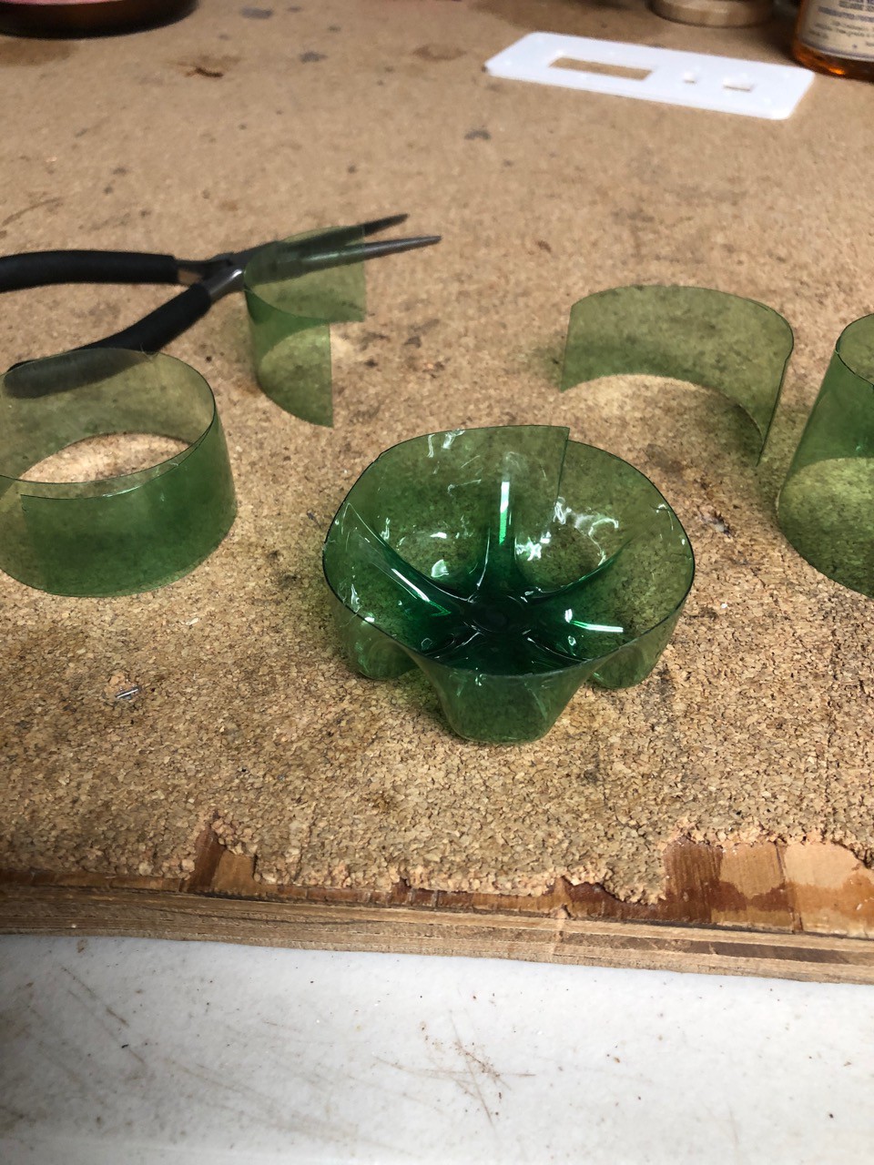
Cutting up plastic bottle for tie downs. This worked extremely well.
Power supplies and Fan mounting
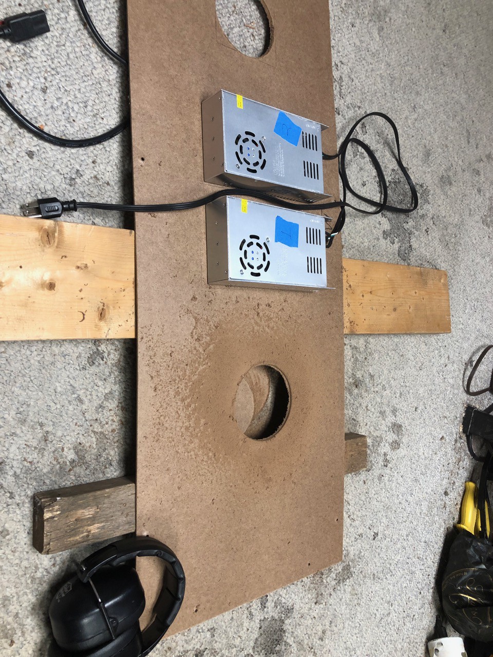
I have the power supplies mounted. The blue painters tape marks them as 1 and 2, I have the power wires labeled similarly.
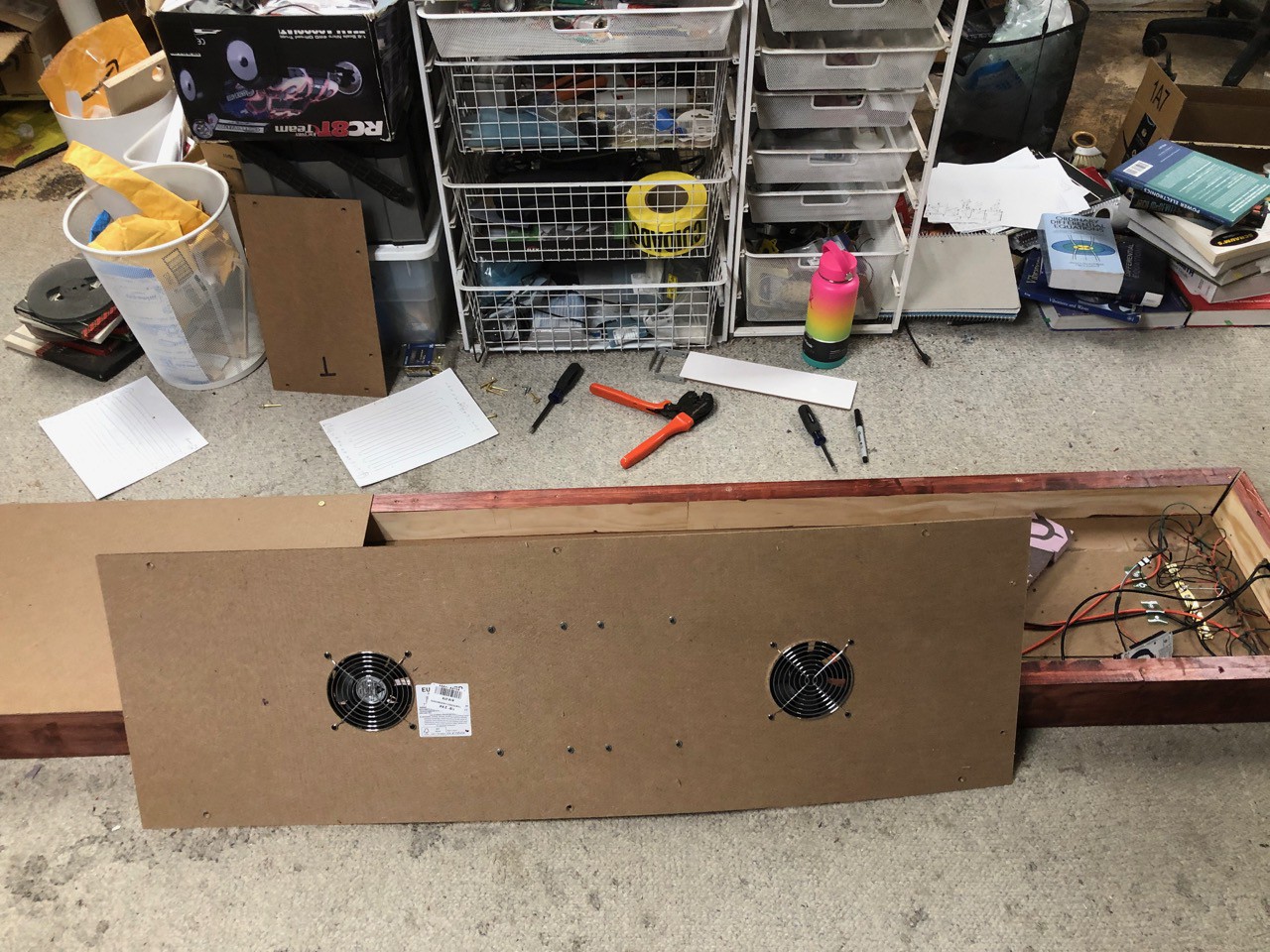
Looking good. Finishing touch is the fan covers. One of the fans is intake and the other is exhaust. The idea is to draw air across the power supplies. I will have foam blocking off the rest of the back of the panel, to get better air flow. Note these fans are 120v.
Connect Panel
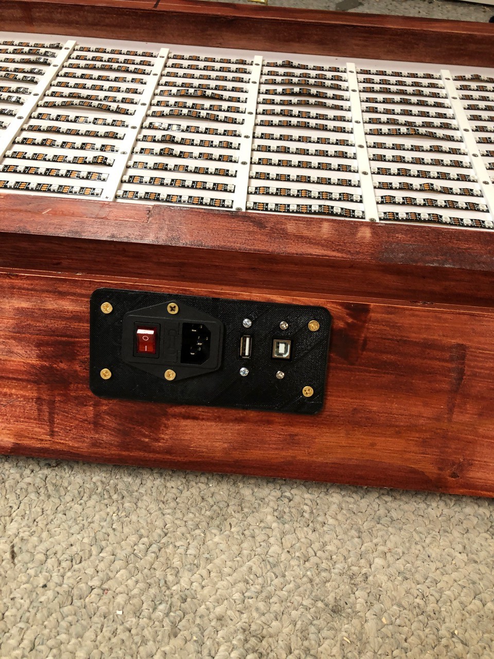
This will be on the side. This turned out very nice. I added a port to be able to update new code on the Arduino. At first I was planning on taking it down and accessing the back panel. This would be a hugh amount of work, not practical.
Discussions
Become a Hackaday.io Member
Create an account to leave a comment. Already have an account? Log In.