 Trevor R.H. Clarke
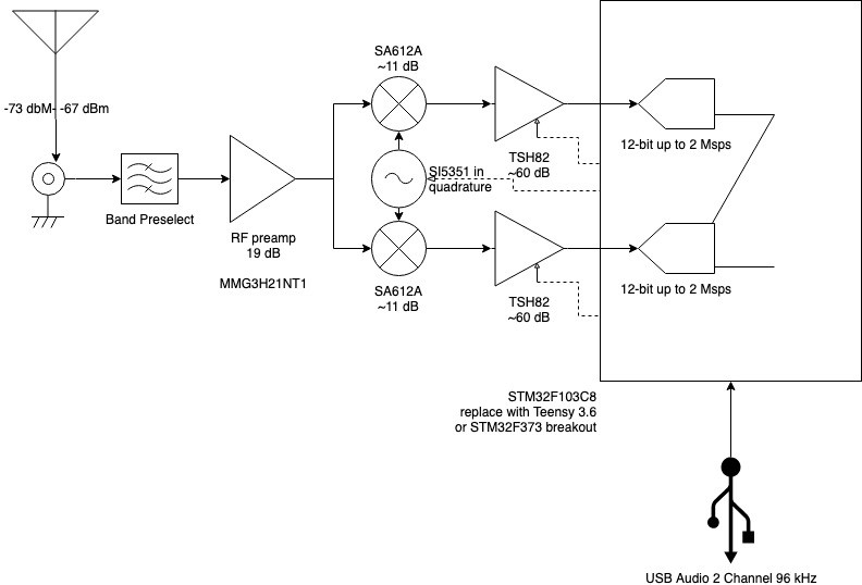
This is the block diagram for the receiver portion of the radio. I've filled in some parts I'm going to try and some hopeful gain numbers. I'm going to try a direct conversion receiver first and see if I get usable data for the low signal modes.
First, the antenna goes right into a bad pre-selector. This will likely be a changeable component. It'll be pretty tight for the initial digital mode implementation, just the CW portion of the expected band. This should drop the noise figure significantly. It will also help with image rejection if I end up having to change over to superhet.
The RF pre-amp will use the monolithic RF amp and should provide on the order of 19 dB of gain which will split to the two mixer sections, one for in-phase and one for quadrature. I'm factoring in 3 dB loss here which should be a good enough for ball park estimates.
I'm going to try an SI5351 a shot. It's a clock generator so there will be some noise introduced because of the square wave harmonics but a lot of people have had good results. It's easily controllable with a microcontroller and it's possible to set the phase of the output signals allowing for direct generation of the I and Q LOs. I'm not sure what the phase distortion will be so this will be an experimental point.
I'm estimating the power at this point will be between -46 and -67 dBm given a 50 to 100 µV signal from the antenna. I sampled a general purpose op-amp from TI. The TSH82 is billed as a high bandwidth video op-amp. It's got a minimum large-signal voltage gain in the 70+ dB range so it should be able to give the 60 dB I think I'll need to reach 1.1 V at the ADCs. This will need to have some trim resistors to balance the I-Q signals but otherwise it should work pretty much as-is. These are only $3 or so in single quantities and they are dual devices so only on IC should be needed.
Initially I plan to use a STM32F103 breakout board, sometimes known as the Black Pill. It's very inexpensive, about $2 a piece from Chinese suppliers. The ADCs are 12-bit and can push 2 Msps, although a more realistic number for this application is probably about 500 ksps which is still about 5 times the 96 kHz I'm going to try and sample. If I lower the sample rate and pull a much smaller chunk of the spectrum around the digital channels, I can oversample and clean up the signal significantly. The F103 has some ADC modes that support DMA and synchronized sampling so I can ensure the I and Q are properly aligned. I'm planning on using the USB audio profile to publish a 96 kHz stereo signal for processing in SDR software. The middleware from ST doesn't support the newer USB audio profile with higher sample rates but I don't think it will be a problem. The plan is to eventually take the PC out of the equation and do all the processing on the micro.
The F103 doesn't really have the processing power to handle the DSP functions, but there's a STM32F373 device with an M4F core with ARM DSP extensions. It's also got 16-bit ADCs for increased sampling resolution. I found a breakout board on Oshpark for $10 but it's just the board. I grabbed a couple of samples of the micro as well (I think it's about a $5 or $6 part normally in single quantity). This probably puts the full board in the $20-$25 range. Another option is to get a Teensy 3.6 for about $10 more. It's a proven SDR board with a similar Cortex M4F. It has an easy to use Arduino DSP library and it's already assembled. It'll push the cost about $50 for the radio but might be worth it anyway.
I'm just waiting on parts to arrive to do some prototyping. If it looks like I'm getting decent amplification and noise statistics, I'll put together a proto PCB.
Discussions
Become a Hackaday.io Member
Create an account to leave a comment. Already have an account? Log In.