 Dylan Brophy
I spent an all-nighter making a simulator for the card, which can load the schematic from KiCad, then spent an egregious amount of time in the sim making the card work. As promised last log, I will show a bit more on the simulator:
For those that prefer reading over watching, I'll do some brief explanation of the simulator, then go over the card itself.
About the Simulator
The simulator loads the KiCad PCB file, constructing a netlist and list of components. There's a (small) component library, which has a simulation model for each component type. The simulator schedules chip updates based on each IC's propagation delay, so the simulator should be largely accurate from a timing perspective too.
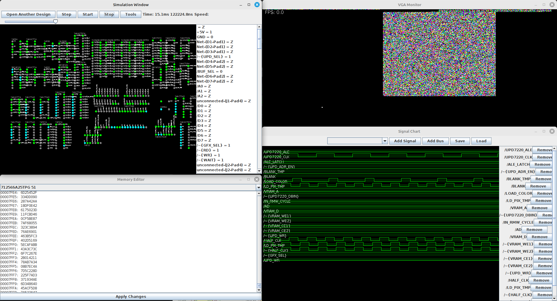 The simulator has some handy features for graphics devices particularly, for example, a VGA display simulator. In the picture, there is a white dot on the VGA display - that is the position of the electron beam at this particular tick. The sim was definitely engineered to my particular use case. Well, I'm pleased with it and hope to use it in projects in the future. Now I can know if a board will work before I order it.
The simulator uses a lot of bit manipulation, and for this reason, it does not at all support analog signals at this time. It's great for simulating logic chips and RAM - or really any ICs that are digital.
I also connected the simulator to my Teensy 4.1, so I could run a simulation with the software in the loop. You can see that in the video up there as well.
Oh, what is that I hear? You could have just used an existing simulator!! Really? Huh, I guess that didn't seem fun enough, well, too late now anyway. Well, here's the source code, if it is wanted: https://git.nuclaer-servers.com/Nuclaer/kicad-logic-simulator
But also, I don't think an existing simulator would have all these features I wanted, and honestly, building this sim didn't take *that* long. I'm really amazed I did it as quickly as I did; I would have expected it to take at least twice as long to write a program like this.
I love MUXes
I replaced many of the logic gates with MUXes, as it is a lot easier to understand what the logic is doing, and the logic is just so much more flexible this way. I got the idea from LUTs in FPGAs, which work in a very similar fashion. The MUXes can accept quite a lot of inputs if you're creative, since you have select lines, enable lines, and inputs - this can afford you a lot more logic per chip than logic gates.
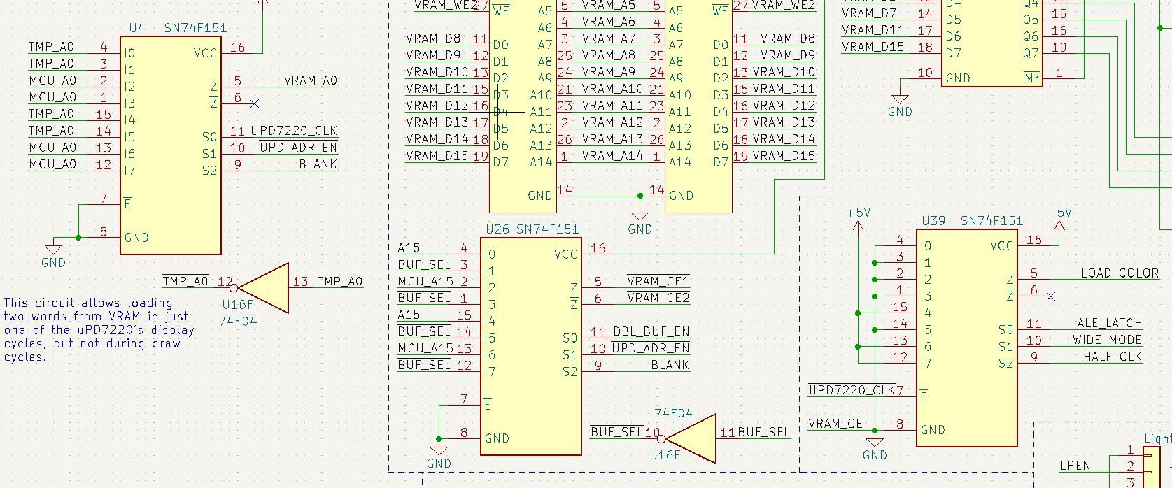
I think I went over this in my last log but I don't remember; well, I needed to change the RAM ICs. The speeds on this board are extremely fast, with a maximum of a 32Mhz pixel clock. I needed RAM that could read/write in less than 30ns for the card to have the whole display written fast enough from the Teensy (or whatever other device). Hopefully I did my math right because I already made the card use different RAM ICs, and these are blazing fast, at 25ns. Unfortunately, this dramatically reduces the maximum graphics memory, which is now 128K (up to 262144 pixels). These numbers are halved if you use hardware double buffering. This limits the highest resolutions to 640x400, or 540x480, for example. This bothers me, so maybe I'll have to make an upgraded card in the future.
For reference, here is the RAM chip I'm using now: https://www.renesas.com/us/en/document/dst/71256sa-datasheet
Schematics and Other Details
I think the design will work, based on the simulation, so I'm finally uploading the schematics after this log is posted. This time I'll add the component libraries and such too, so there will be less issues a few years from now in KiCad 11.0, or whatever will be brewing by then.
Discussions
Become a Hackaday.io Member
Create an account to leave a comment. Already have an account? Log In.