Close
0%
0%

The $50 Ham: Dummy Loads

A couple of cheap dummy loads for testing radios

Similar projects worth following
This is the first of what I hope are many homebrew projects in support of my "$50 Ham" series on Hackaday. Since I'm new to amateur radio homebrewing, we'll start with something simple and useful: dummy loads, which are used in place of antennas to test and adjust transmitters.

Here I present two designs, both probably overkill when you can pick up cheap 50-ohm dummy loads for a couple of bucks. The first is designed mainly for handy talkies like the Baofengs, and should be good for the 2-meter band and above. The second one is a more traditional "paint can" load with a tap for measuring the power your transmitter is putting out. This one will be good for higher wattage, and if I'm careful about stray inductance it should be OK through the 2-meter band as well.

Dummy loads are important tools for hams that are into homebrewing, but they have applications beyond building your own radio. There are just times you need to transmit without radiating, and that's when you need to pull out a dummy load.

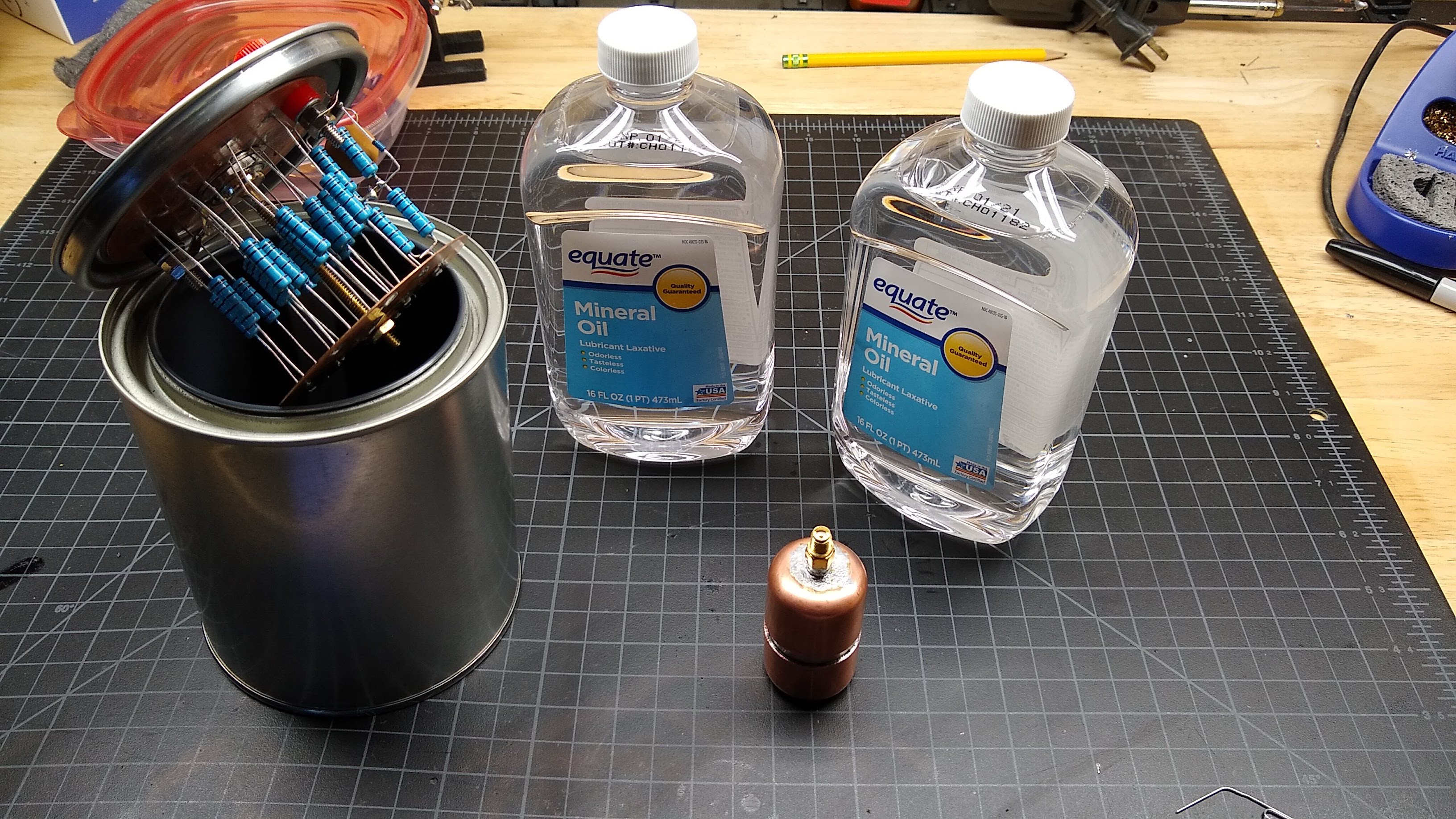
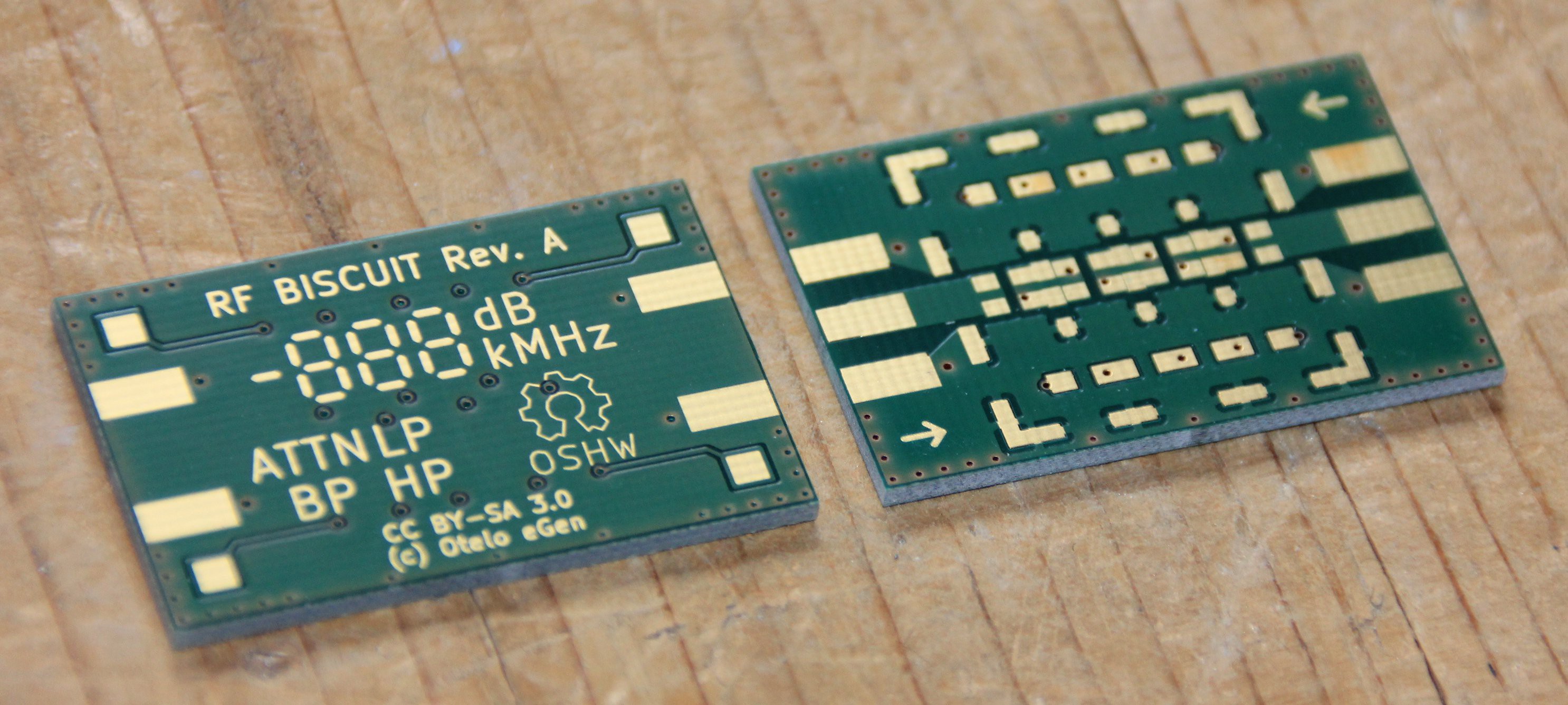
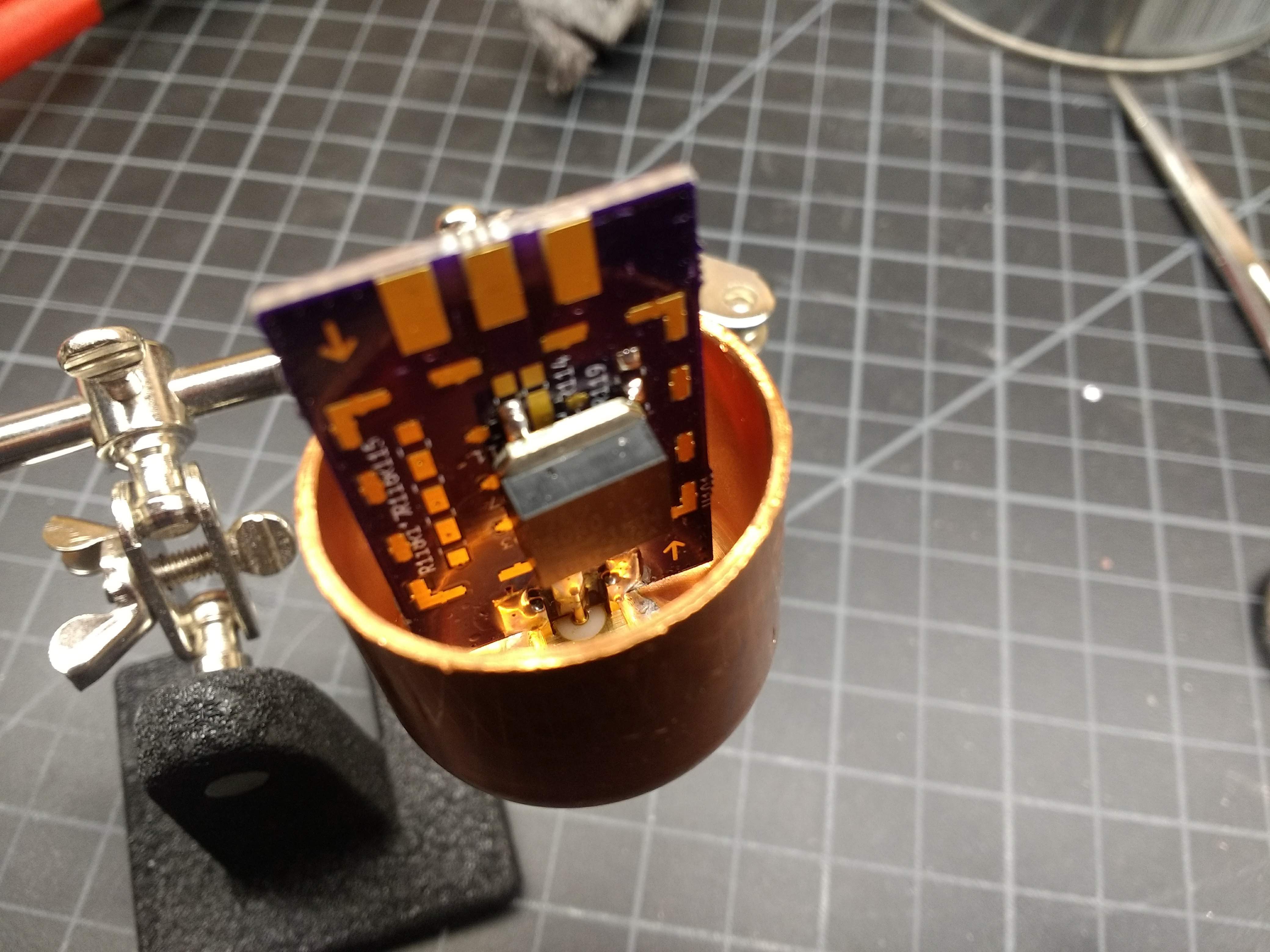
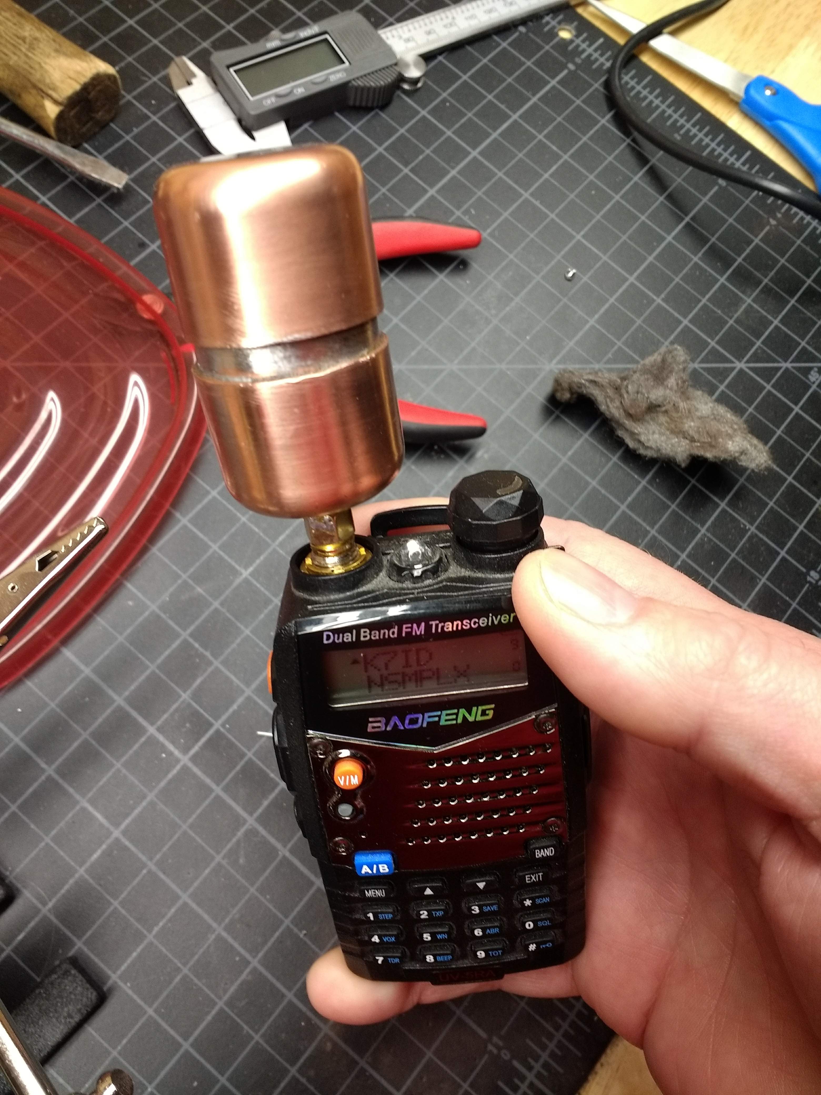
I'm going to be building two dummy loads here, both on the cheap. The smaller load is called L'il Dummy, and it's specifically for small handy-talkies (HTs) like the Baofeng. It'll be capable of sinking 5 watts and should be good for at least the 2-meter band. It'll be a metal-film power resistor mounted to an RF Biscuit board with an SMA connector for hooking directly to the whip antenna connector on the HT. I'll put it all in a nice little case made of copper pipe, because I like copper. I'd like to fill it with mineral oil for better heat conduction, but that might be hard to do. 

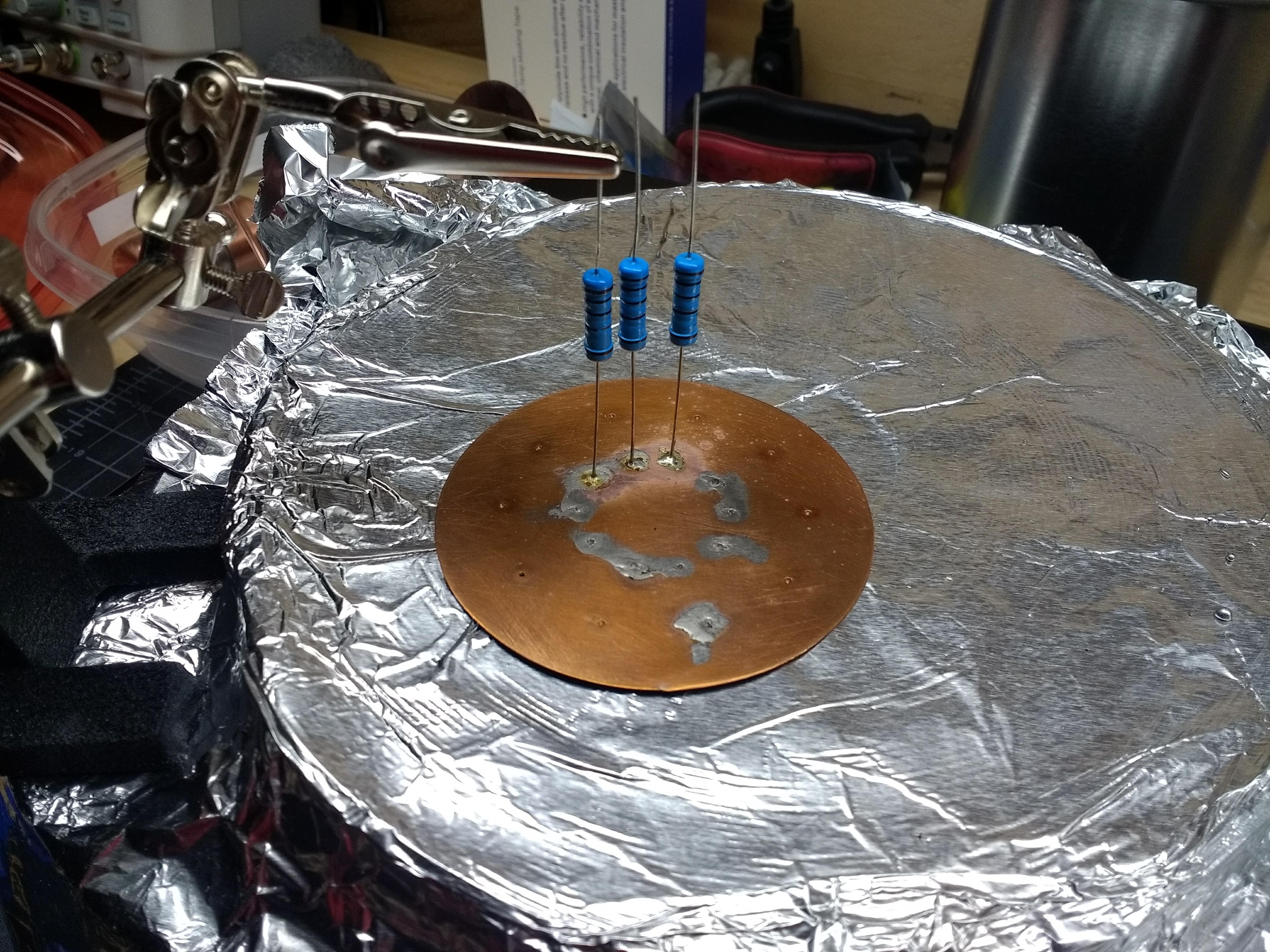
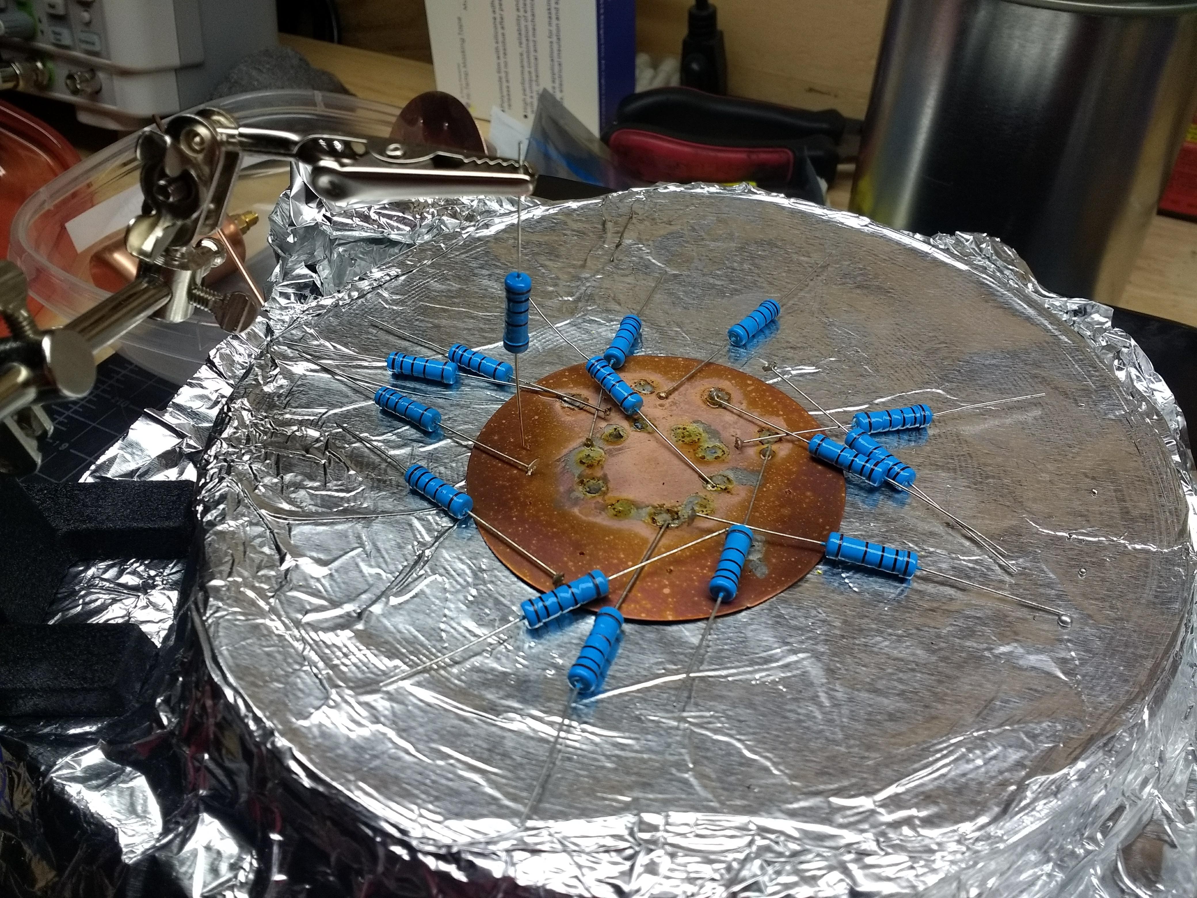
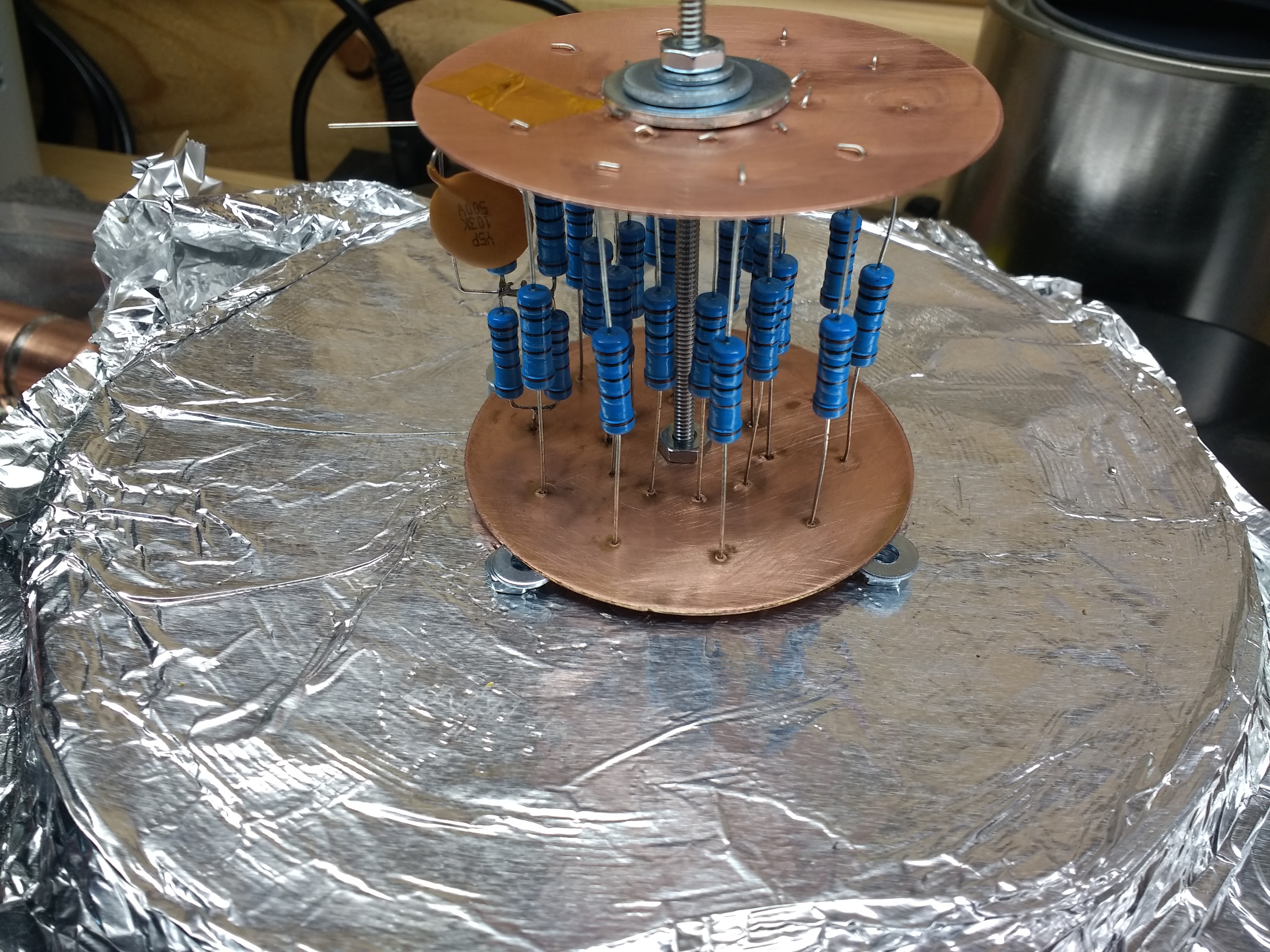
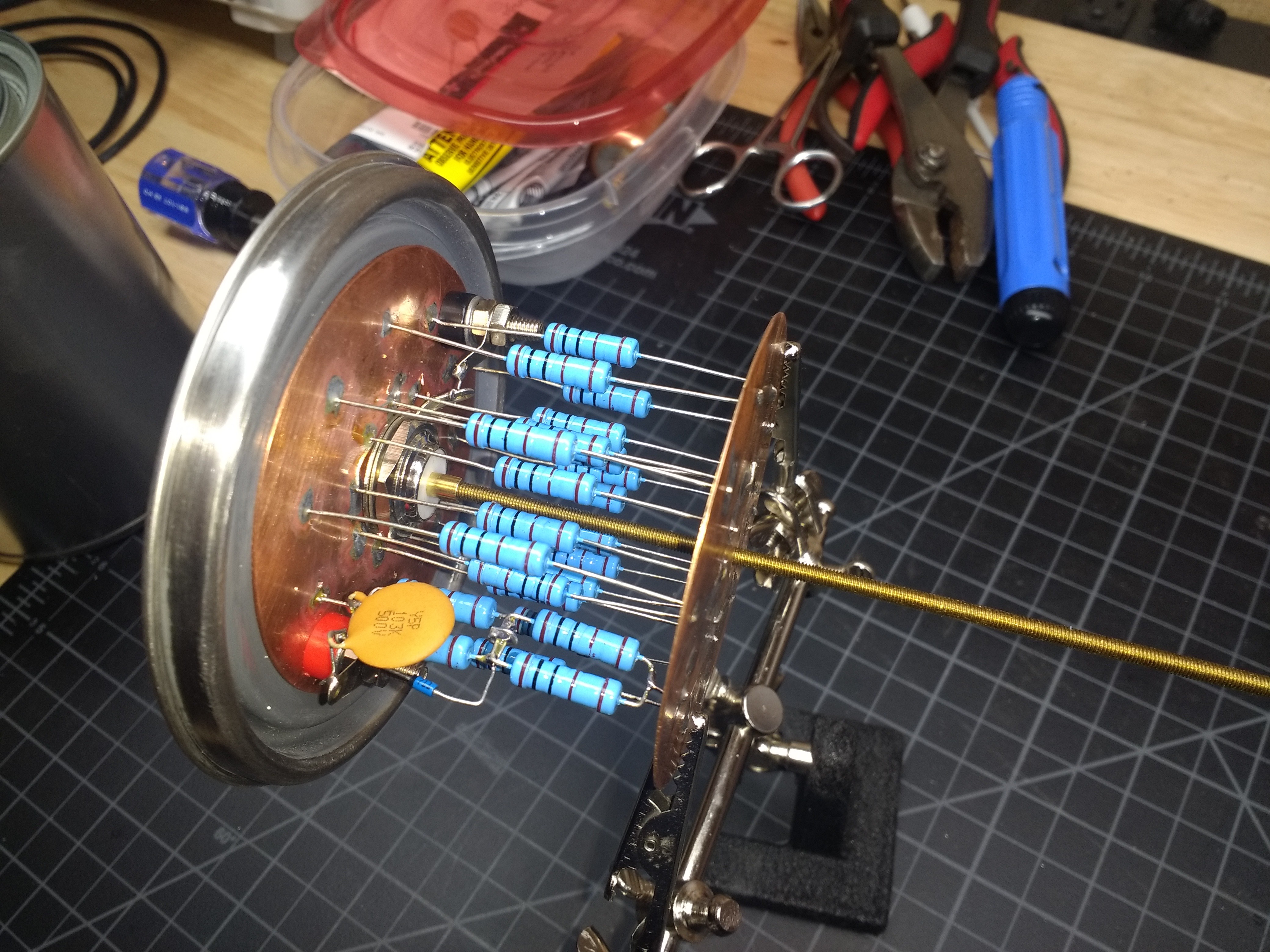
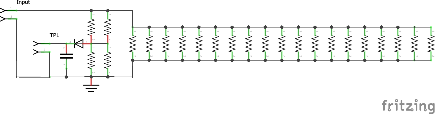
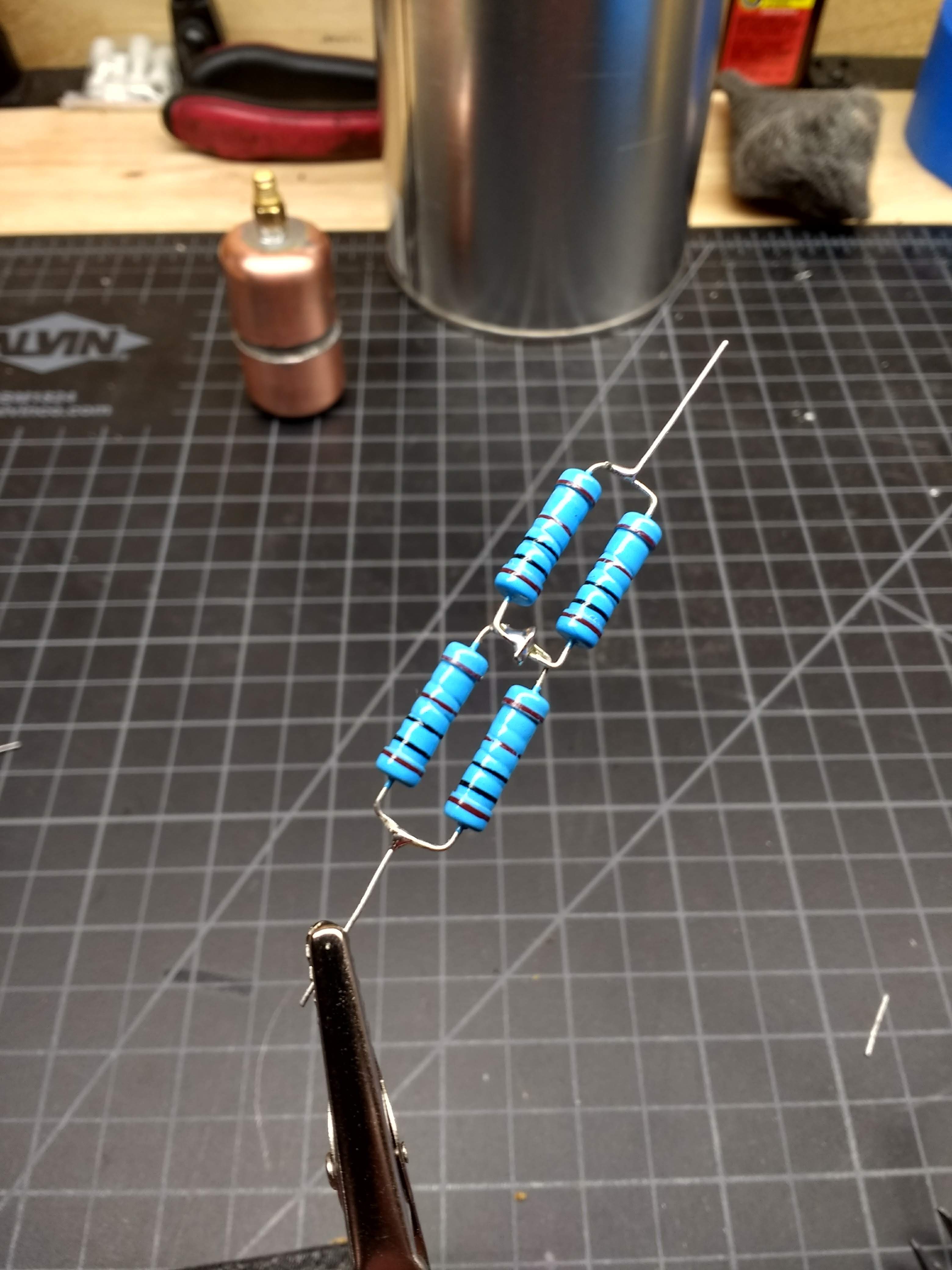
Big Dummy, on the other hand, will be a bit more complicated. This one will be built to handle 40 watts using a bunch of 1k power resistors in parallel. They'll be connected to low-impedance copper plates and suspended in a small paint can filled with mineral oil. I'm also planning a tap for making power measurements. The load should be good for the HF bands and into VHF, and maybe even UHF. Although I'm not exactly sure how to quantify that yet.

  • Big Dummy, Part 2 - The (Un)Soldering

    Dan Maloney04/22/2019 at 00:14 0 comments

    So, how exactly does one make 40 solder connections to a pair of big copper plates?

    I puzzled over that one for a while. I had cut two discs from the copper sheet, about 3" in diameter. I used Fusion 360 to make a template for the 20 holes I'd need, pasted it onto the copper, and punched some holes with a transfer punch. They didn't pierce the copper, but I thought that would be fine - each dimple could hold a lead while I used my big soldering gun to heat it up.

    Nope. Nowhere near enough heat. 

    Plan B occurred to me while waiting in vain for the soldering gun to heat up the copper disc: if only the disc were just below the melting point of solder, I could just push it over the top with a regular iron. So I bought a cheap hot plate at Target and gave it a shot. It was promising:

    You can practically see what's coming. But I couldn't - I happily soldered away, pleased with my cleverness. I got to resistor number 13 before I learned that cheap Target hotplates don't exactly have PID loops to control their temperature:

    Still, the basic idea was somewhat sound. What I came up with was building the whole thing first, then soldering it with all the resistors mechanically attached to the plates. This required through holes of 0.6-mm, which meant I had to buy a pin vise and small bits. But with everything secured, the soldering went much better:

    A length of 6-32 threaded brass rod holds the final assembly together and connects the center conductor of the SO-239 jack to the bottom plate. Here it is before trimming off the rod and soldering.

    The end of the threaded rod needed a little turning down before it would fit in the SO-239 solder cup. Lacking a lathe - sigh - I chucked the rod in my drill and spun it against a file. A couple of brass hex nuts finished the connection to the bottom plate and Big Dummy was ready for an oily dunk.

    It tool most of two pints to fill the can. I haven's had a chance to test it yet - my big HF rig isn't set up now. More to come

  • Big Dummy

    Dan Maloney04/11/2019 at 15:57 0 comments

    Turns out that soldering 20 resistors between two big plates of copper is a non-trivial task. Who'da thunk?

    The design goals of Big Dummy are a little grander. What I wanted was a dummy load with more power handling - 50 watts preferably - and a way to tap off the transmitter's output so I can make some measurements. I also want to make a "Cantenna"-style load - built into a paint bucket and filled with dielectric oil for cooling. I don't know why - it just seems cool. Plus, I want the thing to be usable not just in the HF bands but hopefully also at VHF and maybe even UHF. Lastly, I want it to look good.

    After looking at all sorts of designs and searching for cheap and easily available components, I settled on 20 1-k thick-film resistors in parallel. That gives 50 ohms of impedance, and with 2-watt resistors, that should dissipate 40 watts - close enough to 50. My plan was to build it into a small (one quart, or about a liter) paint can. I wanted to suspend the resistors between two copper plates for low parasitic capacitance and good power dissipation, so I ordered up some 24-AWG copper  sheet off Amazon. It's about 0.5-mm thick, which doesn't sound like much but. it's more than enough. I had no idea going in how hard this decision was going to make the project.

    For the testing connection, I modified a design from K7AGE that's pretty simple. His dummy used eight 100-ohm power resistors in a series-parallel arrangement to get 50 ohms total. That allowed him to tap off the center of two of the series resistances, treating them like a voltage divider. That goes to the test point through a 1N5711 Schottky diode, with a small ceramic decoupling cap across the test points.

    I suck at EDA software - so far - so I just did a quick Fritzing schematic:

    All I had was 1000-ohm resistors, so I had to do a series-parallel network to provide the voltage divider needed for the test point. That was a fun bit of soldering:

    I dig circuit sculptures...

    While soldering these, i noticed that the appeared to be wire-wound - see the spiral grooves? I destructively tested one, just to be sure they were actually metal-film:

    Yup - solid slug of material. The grooves must be how they fine-tune the resistance.

  • L'il Dummy​

    Dan Maloney04/11/2019 at 15:56 0 comments

    The basic design for this dummy load comes from the RF Biscuit project by @georg ottinger. It's a simple PCB design that has pads for SMA edge connectors at each end, a ground plane around the whole board, and pads for placing SMT components in arbitrary combinations to build up filters, attenuators, and amps for RF use. I downloaded his design and had three boards printed up at OSH Park for a couple of bucks. I have a couple of things I want to try with these boards, and the first is a 50-ohm dummy load for my handy-talkie (HT).

    The circuit for a dummy load is stupid (heh) simple - it's literally just a 50-ohm resistor across the antenna connector's inner conductor and shield. But, as with all things RF, details matter. Not just any resistor will do. First, it has be able to dissipate the power that the radio will put through it - 5 watts in this case. That means you need to spec a power resistor, which more often than not are wirewound. No bueno - that looks more like an inductor than a resistor to an RF circuit, and things will start to get twitchy. What to do?

    We need a non-wirewound, 50-ohm power resistor, preferably in an SMT package. Luckily, @georg ottinger lists a thick-film, SMT resistor that can dissipate a whopping 35 watts - a Bourns PWR263S-35-50R0F. I picked one up off of Mouser for less than $5, and sourced some card-edge SMA jacks from Amazon to complete the internals.

    I soldered up the board and gave the dummy load a test on my Baofeng. To my surprise, the dummy was almost as effective an antenna as the stock rubber  ducky - I was able to hit a repeater a couple of miles from my house! Clearly this is not how a dummy load is intended to act. I figured a decent enclosure would help, so off to Home Depot.

    My idea was to case everything up inside a small length of copper pipe. The RD Biscuit board fit nicely inside a 1" diameter copper pipe, so I bought a short length of pipe and two 1" caps. Copper is crazy expensive, which sucked a little since I only need a piece of pipe like 3/4" long to couple the two caps together. I drilled a hole in one cap for the SMA jack, polished everything up nice and clean and fluxed the crap out of it, then tried to solder it in place. I had to move up from my Weller soldering gun to a propane torch, and there was a lot of juggling around hot copper and molten solder, but in the end I got it soldered together. 

    Doesn't look half bad cleaned up:

    I had intended to fill the case with mineral oil before soldering it up, but I couldn't figure out how to do that. If I had somehow marked the position of the board inside the pipe I could drill a small hole in the top cap and fill it now, but why bother? The resistor is rated at like 7 times what this radio and any of the HTs I'm like to own can radiate, and even if the resistor gets a little warm in use - and it does - it's no big deal. I'm leaving well enough alone.

    Double checked the dummy load and it now does exactly what it's supposed to do. I also checked it on an SWR meter and it's behaving just like it should. L'il Dummy seems like a success - my first ham radio-related build worked! W00t!

View all 3 project logs

Enjoy this project?

Share

Discussions

Brian Bowling wrote 01/20/2021 at 22:39 point

What is the best way to drill the tops/lids of those paint cans so that they don't tear out?

  Are you sure? yes | no

Dan Maloney wrote 01/20/2021 at 22:50 point

What I did was to clamp the thin metal of the lid between two thin pieces of wood and drill through the whole thing together.

  Are you sure? yes | no

Brian Bowling wrote 01/21/2021 at 03:27 point

Thank you!

  Are you sure? yes | no

Mike Szczys wrote 04/22/2019 at 17:19 point

"Probably overkill" is my favorite kind :-D

I"m really enjoying following along... I'm learning a lot since I know next-to-nothing about RF. You'll make a ham out of me yet!

  Are you sure? yes | no

Dan Maloney wrote 04/23/2019 at 04:34 point

Why buy something for $10 when you can build it for $50, amiright?

  Are you sure? yes | no

Martin wrote 04/09/2019 at 22:10 point

Oil filled cantennas are notorious for leaving rings of oil where they were sitting.   The oil gets out no matter how well sealed.

  Are you sure? yes | no

Dan Maloney wrote 04/23/2019 at 03:08 point

Yes, I see that now that I've filled Big Dummy...

My leak is from the top, around the SO-239 jack and binding posts. I may have to add rubber gaskets of some sort.

  Are you sure? yes | no

Ted Yapo wrote 04/23/2019 at 03:12 point

solder the top closed :-)

  Are you sure? yes | no

Dan Maloney wrote 04/23/2019 at 04:35 point

Might have to do that. Just worried that the top of the can won't take solder, and that the amount of heat I'll have to apply will be unreasonable.

  Are you sure? yes | no

James wrote 04/24/2019 at 16:46 point

If you're concerned about the heat-load on the can, you could empty the oil out, then drill two small holes on the lid (1/8", 3mm ish) .  Solder around the rim of the can, then refill thru one of the small holes (yes, it probably will take aaaaages).  You can then close the fill & vent holes with much less heat.

  Are you sure? yes | no

Dan Maloney wrote 04/09/2019 at 17:25 point

Yeah, the first time I tested the HT dummy I hit the repeater 10 miles away! Seems better now that it's cased up in the copper pipe.

Cantenna in the works. But what do you mean by leak-proof - RF or mineral oil? Not 100% sure I can get the SO-239 bulkhead connector absolutely sealed - might need a rubber gasket. Suppose I could solder the hell out of it and hope to get a liquid-tight joint. Still waiting on some parts - zener, a cap, and some binding posts for the voltage tap - so it'll probably be a week before I get Big Dummy up and running.

  Are you sure? yes | no

Martin wrote 04/05/2019 at 20:28 point

Extra points for measuring ERP from you dummy loads.   I have a 50 ohm 5 W I soldered to a SMA connector to put on  HTs.  The first time I tried, even with 0.5 W transmitter output I got full quieting on other HTs in the room.  Then I took the antenna off the the receiver I still got good copy just from the RF leaking into the radio.

 Sorta related: http://qrper.com/2018/11/the-2019-lightbulb-qso-party/

Also extra ports for a leak-proof cantenna.

  Are you sure? yes | no

Similar Projects

Does this project spark your interest?

Become a member to follow this project and never miss any updates