The Thor robot has a ball bearing in its base called: 16014. That is one giant ball bearing but it must carry 6 stepper-motors the weight of the arm and payload.
This ball bearing was ordered on Amazon but later cancelled as undeliverable. So I had to find a different shop that sells these ball-bearings that had it in stock and was good in price.
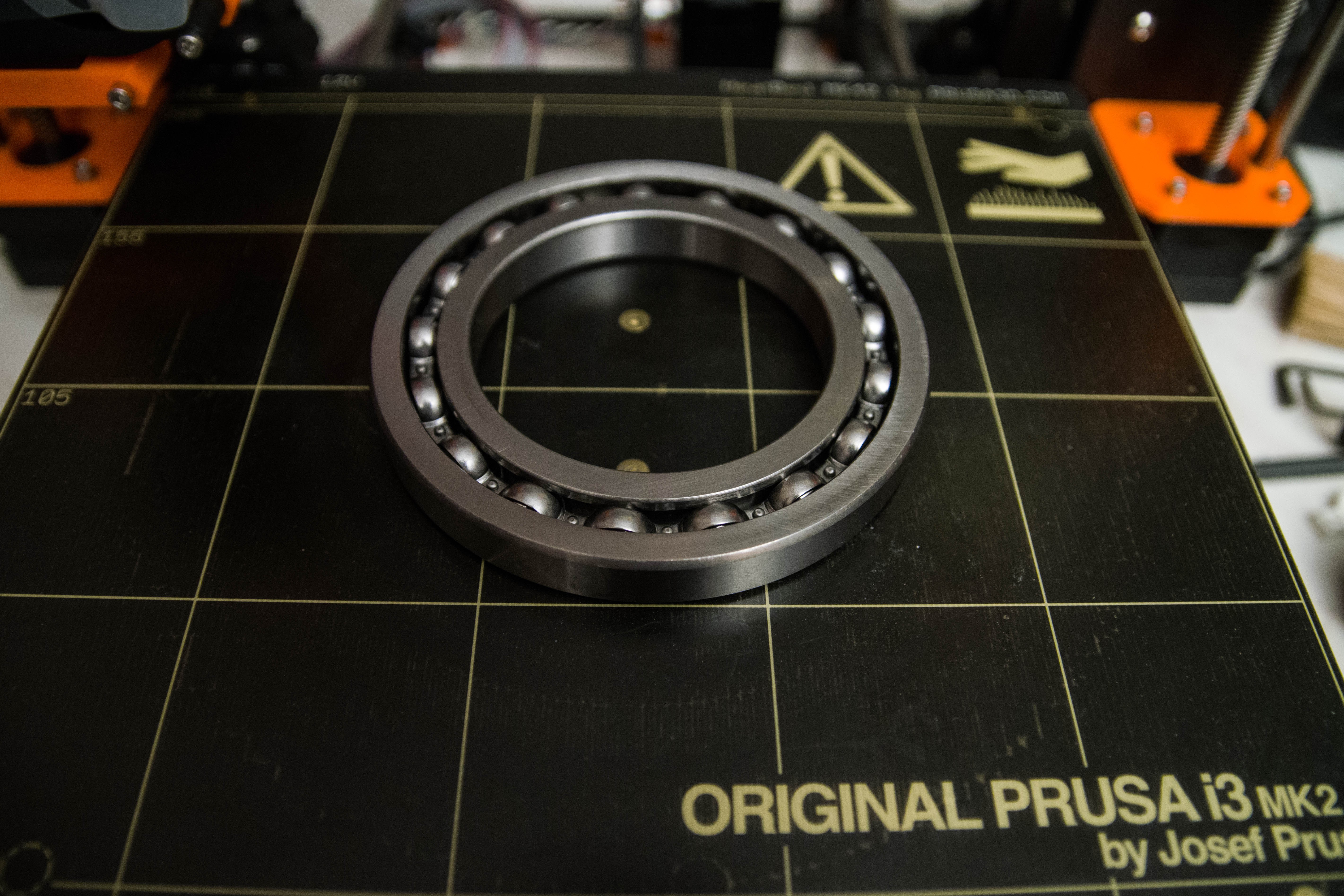
Put on my 3D printer so you can get a feeling of how big that thing is. The cost was €37 total including shipping and VAT.
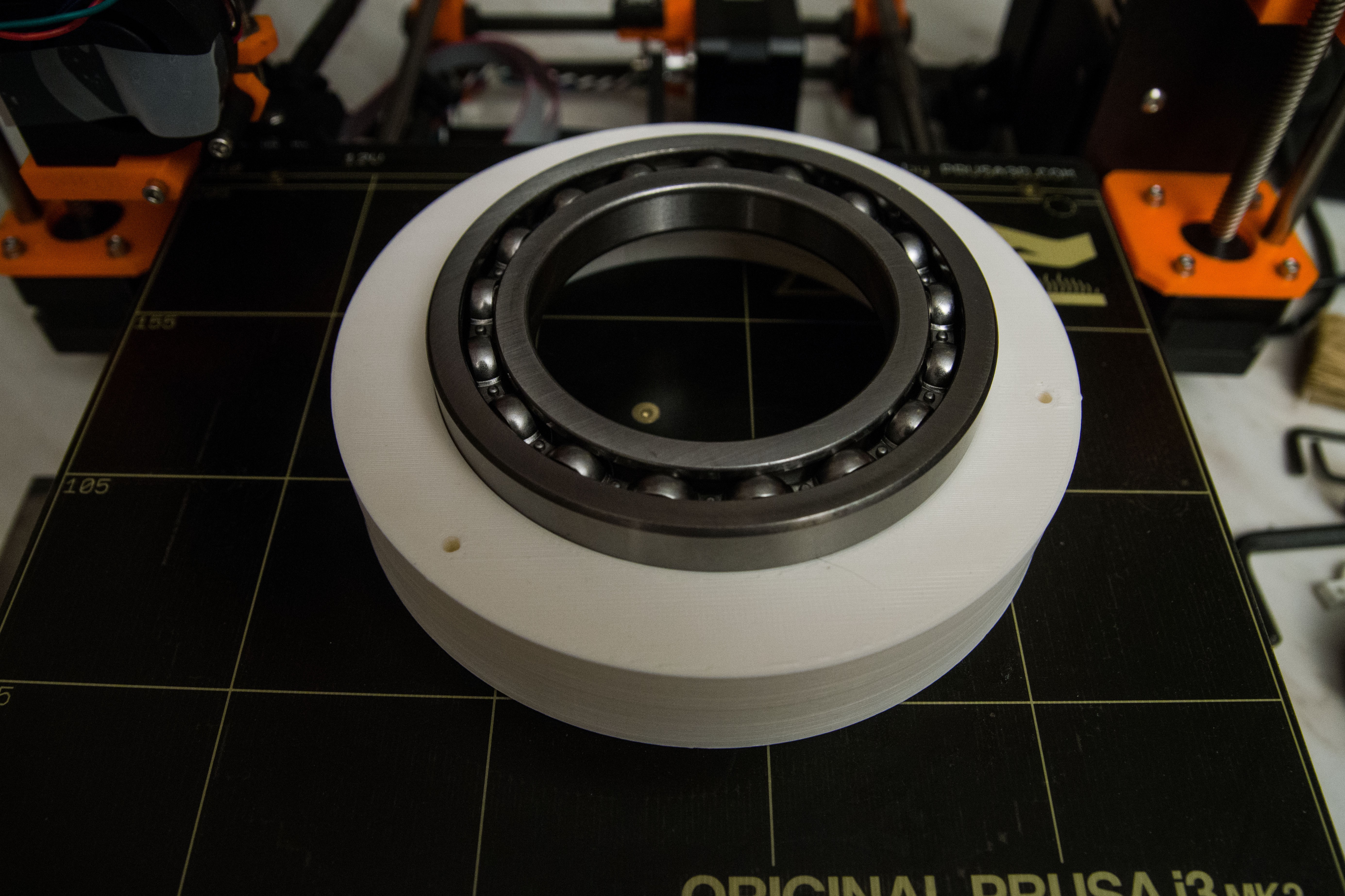
The bearing is intended to fit in BaseTop01. I noticed that it does not fit into the 3D print so I am guessing that I have to scrape off a bit of the plastic.
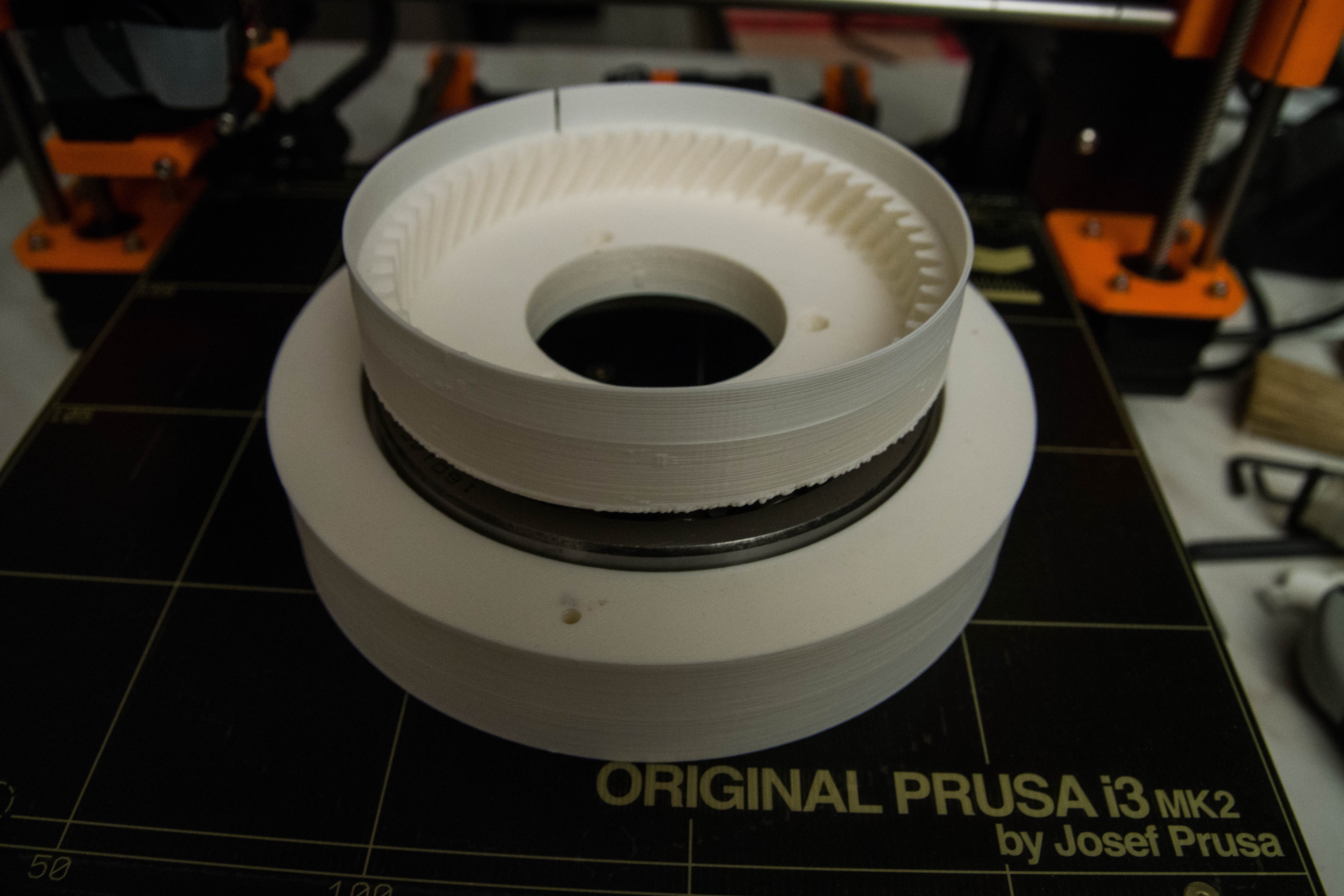
This part is upside down in the real Thor robot. Imagine that the ball bearing is fully inserted into BaseTop01 then Art1Bot fits into the inner hole (that one does fit). You can see the photo cell light split and the cogs that will be driven by the Base motor.
As Danny warned me, it should be painted black otherwise the light detector will get wrong signals because the plastic is transparent. Thanks Danny!
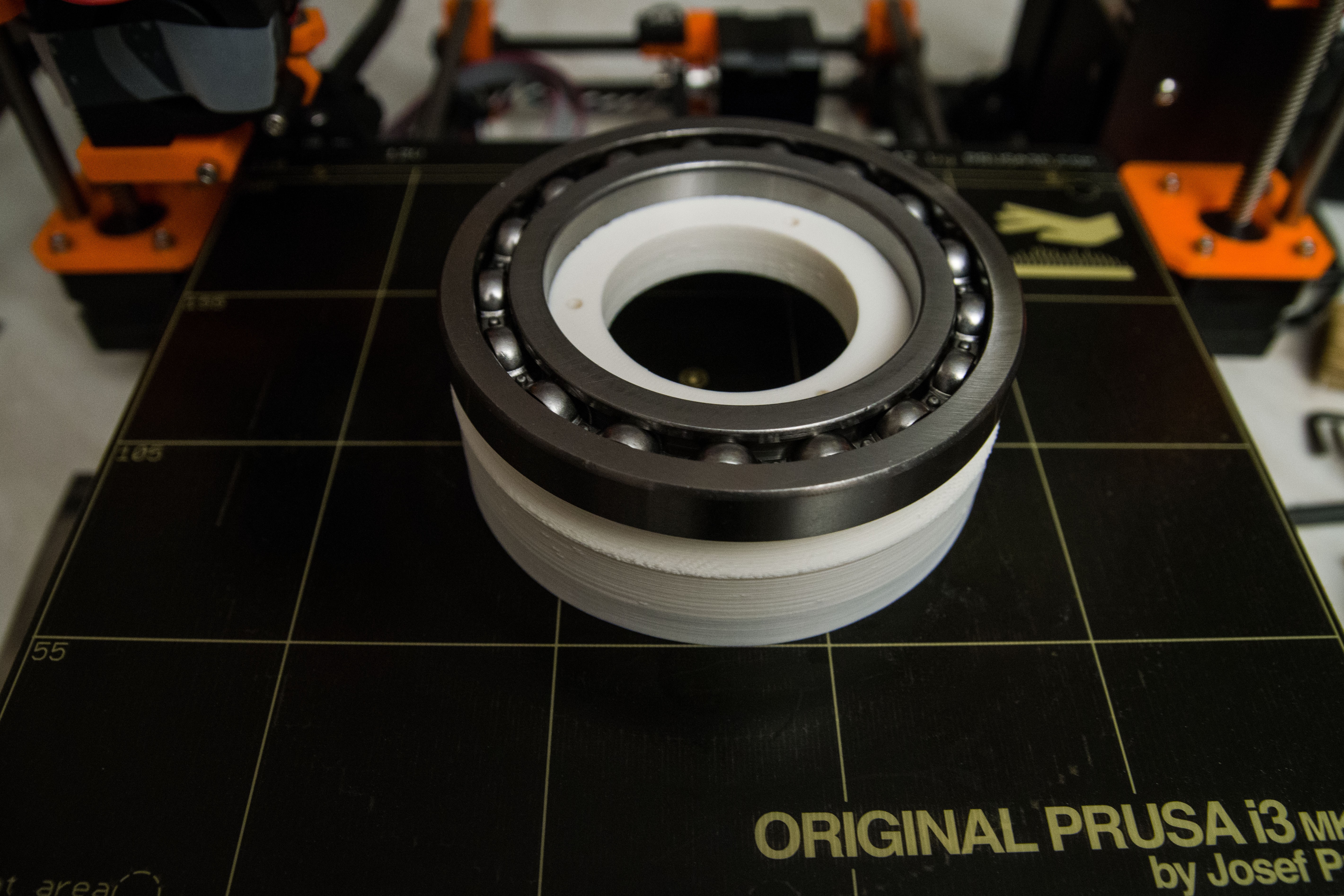
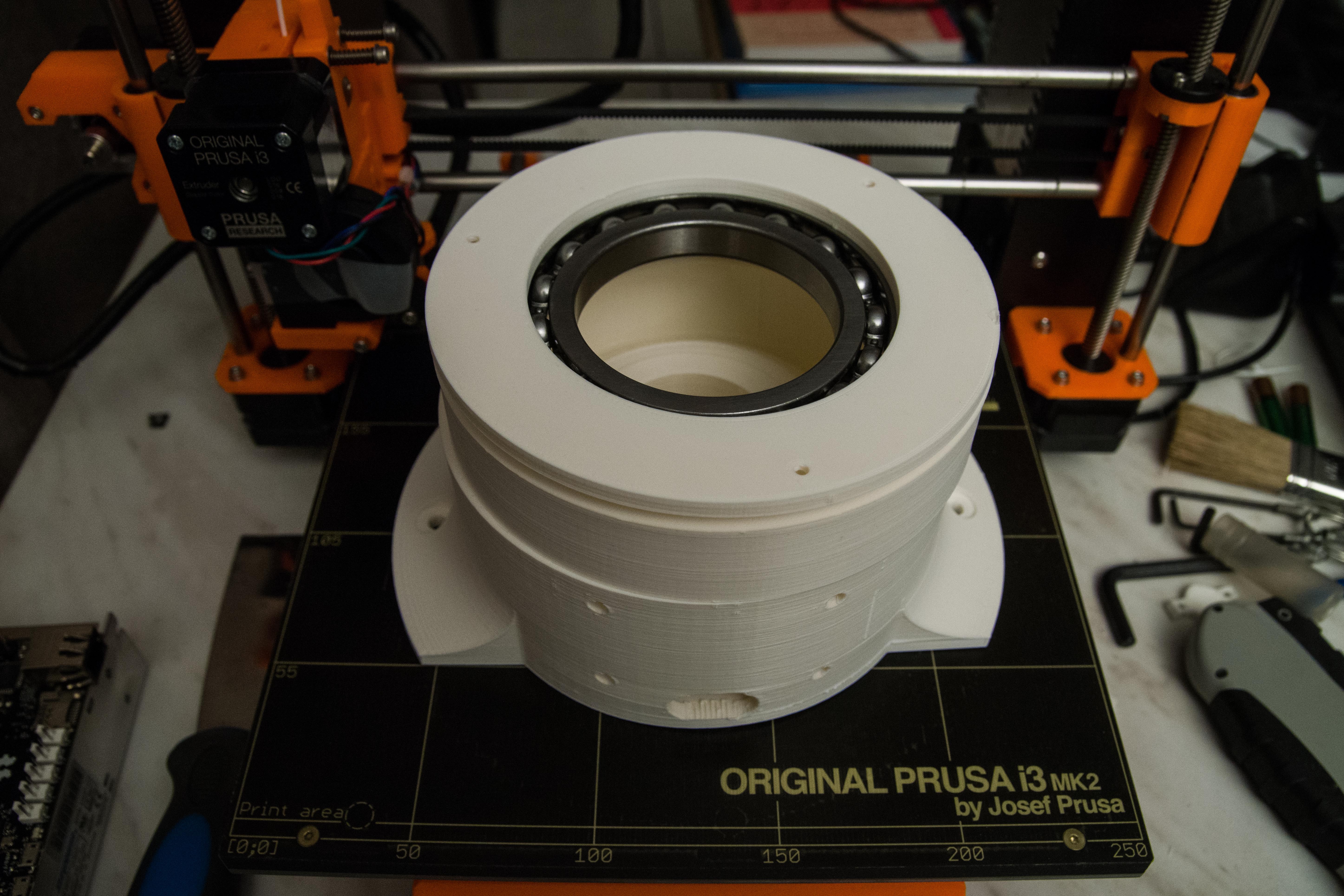
Partially lose assembles as a trial to get an idea how it is going to be assembled once I get the ball bearing inside the 3d model. I have some scraping to do.
The Base print is from Danny's model that already has cut out parts in the base for a controller and wires.
One remark, I have noticed that the base stepper motor draws 2.2 Amperes. I think we need some holes in that base part because I expect it to be getting hot.
Discussions
Become a Hackaday.io Member
Create an account to leave a comment. Already have an account? Log In.
Where is my sledge hammer? :-)
A question about these stepper motors. When do they draw the most power? When they move or are standing still? I have understood that the stepper drivers will regulate current and use voltage to drive the motors. But when they are standing still (but enabled) do they much draw power?
Are you sure? yes | no
I know, when they are standing still and enabled they will be warming up, it's sad that they don't have a brake. In my positioning routine you can enable (lock) /disable (unlock) the motor when it's on position. For the base movement this will be a solution, but when they need the hold the structure you have to keep them enabled (locked). I have to experiment if it will be needed with the geared motors, maybe they are strong enough to hold it. The power (current) will be remain the same when running or stopped. When the motor goes into protection you have no warning, so the robot will fail. There will be the feedback a solution, but that's for later on. Lets walk before we run.
Are you sure? yes | no
When you disable the stepper-motors then the power is cut off but depending on the load the motor might start to slip some steps. I think this will reduce the accuracy of the position of the arm.
Is there a certain position where you have the least used power? Like in full step.
Are you sure? yes | no
Not really,I know when disable the motor you don't have any control of the position anymore, Feeback with a potmeter or encoder is the solution to it. the resolution of steps will be done with the jumpers microsteps 1, 1/2 4 8 16 32. It's the currency of positioning, I don't think it will be make more current. My system is working at 4 microsteps at the moment.
Are you sure? yes | no
The duty factor of the rotating base will be very low in most cases, so we have to test if it's really going to be to hot. For the ball bearing, I had to push very hard, slidly with a hamer to bring in the bearing, it's the currency of the 3D printing. I warn you that the bearing has to be completly inside of it, I had to do it twice because when everything was screwed it was stucked and it could not turn anymore.
Success!
Are you sure? yes | no