If I understand the Thor drawing correctly then Art1Body has an rotation axis along this line.
The whole assembly is pushed together by the intersection (upper right)
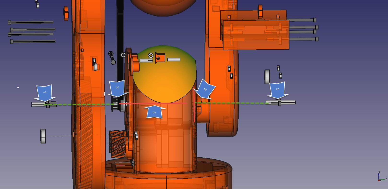
The issue is that I have 2 small 5 mm rods and the motor axis that holds the complete weight. I am wondering if we cannot modify this design so that we have one solid rod and the driving motor shifted up or down with cogs in between.
This would remove the weigh off the stepper motor, and be much easier to montage and balance when it gets a full load.
I like the idea that the upper arm driving motor is in the lower base so that it the biggest weight of the motors is lower to the floor. And when they are together then we only need one cooling fan to cool all three motors.
The lower left motors work in tandem because of the power it needs to move the upper weight. I am wondering if one of the motors cog may be better positioned to opposite side and have a second inner cog at the right arm. That would improve the balance because we have current design has enormous horsepower on only on side, risking the arm to skew one side.
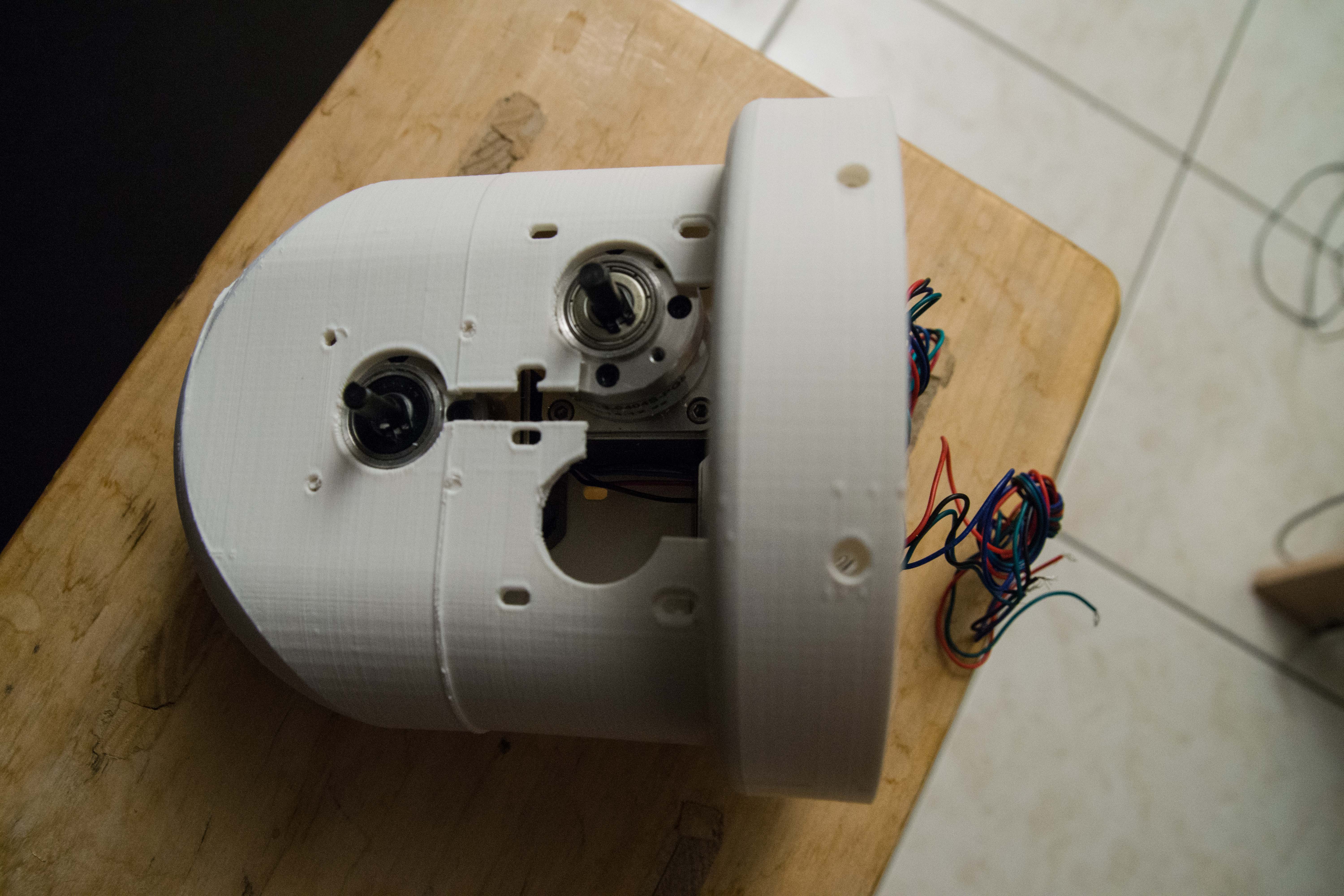
An example of the 3 motors inside the 3D printed housing as a test assembly.
Discussions
Become a Hackaday.io Member
Create an account to leave a comment. Already have an account? Log In.
I like your reasoning, especially when one has to realize that wires also have to run inside this robot to the upper parts.
However you have the only know working prototype. And that is more valuable than reasoning. How well does it behave? Have you noticed wear, tear, warping when you operate it?
Are you sure? yes | no
Hi Olaf,
You did a nice study of second articulation! As you said, the axis of the second articulation is that line you drew, and all the weight is distributed between the motor of 3rd articulation and the bearing inserted in the opposite face of Art1Body piece. Let me share some early thoughts (http://i.imgur.com/vszESbe.jpg):
Case 1: Is the current design. Art1Body has an height "h" and Art2BodyA Inner cog has a "r" radius.
Case 2: Pushing down the 3rd articulation motor. In this case the Art1Body has to grow in height (h'). The axis will be over the motors and the Art2BodyA inner rog's radius has to be bigger (r'). This will increase the total height of Art2Body, but not the total torque because the distance between axis is the same. I think that the 3rd axis' movement transmission should be done using a double pulley situated in the shaft. As r' is greater than r will result in a better mechanical reduction.
Case 3: Pushing up the 3rd articulation motor. As the previous case, the Art1Body has to grow in height. The shaft will be under the 3rd articulation motor and the Art2BodyA inner rog's radius (r'') will decrease, causing a worse mechanical reduction. The 3rd axis' movement transmission should be done as the previous case.
In conclusion, I think the second case is the best option to start with.
About the turning 180º one of 2nd articulation motors: if that is done, Art2BodyB should be modified in order to include an inner rog and the sensor of that articulation have to be moved. Also, I think that it would be harder to drive the wires avoiding the gears. I'm not very into mechanics and I don't really know if that change would make a difference :/
I'll be thinking about it!
Best regards!
Are you sure? yes | no