 Saimon
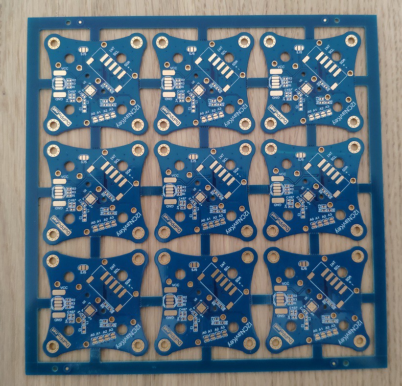
I have run a new PCB batch and i have changed a little bit the design.
First of all the PCB have the ENIG finishing.
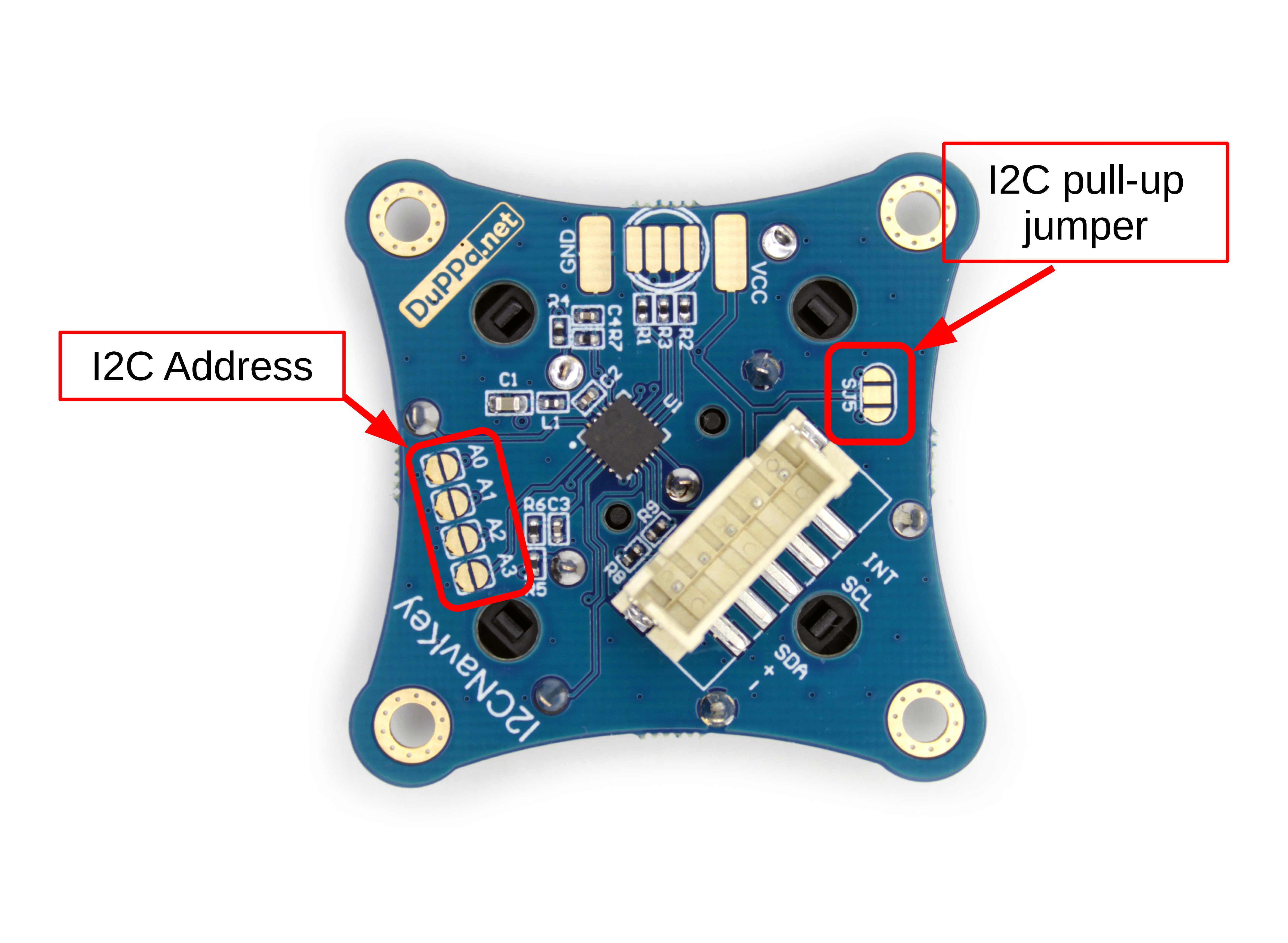
Now the space for soldering the pull-up resistors is gone, instead they are already soldered and can be enabled by shorting a 3-way jumper:
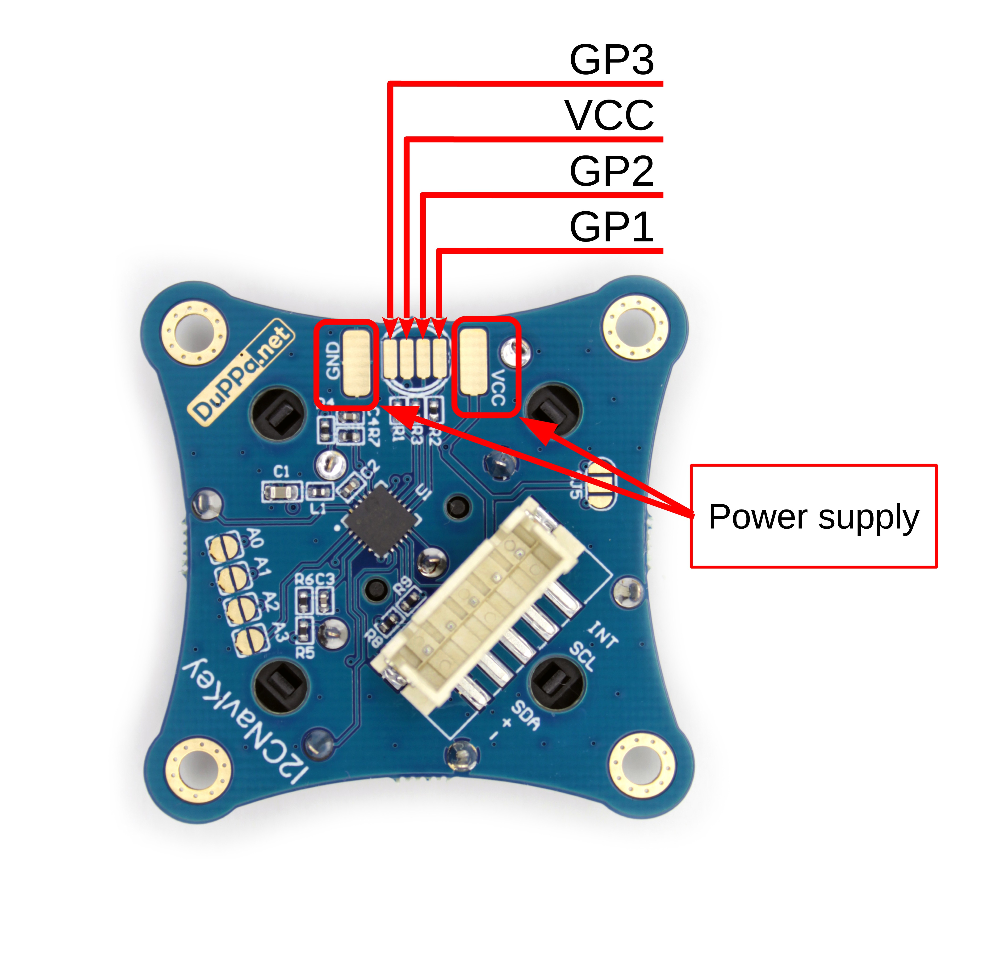
I have also added 2 huge pads for the power supply near the RGB led footprint. In this way is easy to solder some wires for powering something connected to the GP pins.
Discussions
Become a Hackaday.io Member
Create an account to leave a comment. Already have an account? Log In.