 Marcos
That's right, Field Weakening!
A major milestone for the VESC platform! In our public repo we pushed the code to add support to FW to set the motor speed beyond base speed, and Max Torque Per Amp support, intended to drive IPM motors. We'll talk about MTPA in a future episode...
Without field weakening, a motor drive can only operate the machine up to base speed in the plot below. That's the constant torque region, you can achieve full torque in all that speed region, and then torque suddenly drops to zero.

With Field Weakening (FW) now the controller can make use of the extremely valuable constant power region. See it in action:
In the video you can see the Iq (torque generating current) in red, and Id (flux-generating current) in blue. When motor reaches base speed, a negative Id current weakens the field to decrease BEMF and allow more Iq current that produces torque.
Interior Permanent Magnet (IPM) Motors have a mechanically robust rotor structure that is effective in flux-weakening operation because it has low effective air gap. So, IPMSM can be operated not only in the constant torque region under the base speed but also in the constant power region over the base speed, and its the architecture most commonly used by OEMs in Electric Vehicles.
How it works?
As a motor rotates, it creates a back-EMF voltage across its coils proportional to the speed of rotation. In order to force current into the coils, the applied voltage must exceed this voltage.
The limitation comes when the speed of rotation is such that the required applied voltage is greater than the voltage available from the inverter electronics. At this point, the inverter can no longer supply current to the stator coils and the motor will not generate any torque. If the rotor is externally forced to rotate faster, the back-EMF voltage will exceed the power supply voltage, and current will attempt to flow from the coils into the power supply, producing a torque counter to the direction of rotation.
In practical terms, this means that for a given power supply voltage, and a required coil current, there is a maximum speed of rotation obtainable before inverter saturation occurs preventing more coil current from flowing into the coil. This speed is referred to as the base speed.
In order to exceed the base speed, the back-EMF voltage must be reduced. Since the back-EMF is also a function of the magnetic flux between rotor permanent magnets and stator coils, reducing this magnetic flux will reduce the back EMF voltage. The inverter then does not enter saturation, current can flow into the stator coils, and the motor can rotate faster, although at the expense of reduced maximum torque.
The basic principle of field weakening, as its name suggests, is to weaken the magnetic field strength of the rotor magnets, by applying an opposing magnetic field on the stator coils in phase with the rotor field. This is the direct axis (d-axis) in field oriented control, and acts to reduce the back EMF generated by the motor as it rotates.
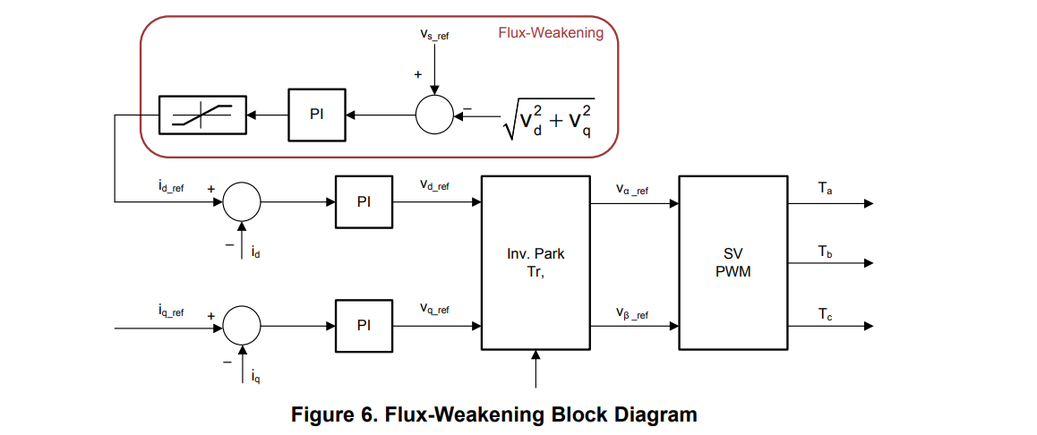
The control scheme chosen to drive flux-creating current Id is based upon the following diagram, taken from a TI app note:
As always, to dig deeper into the new feature, you can check out our Pull Request on the VESC repository:
https://github.com/vedderb/bldc/pull/91
Alongside with the firmware code, we provided the patch for the user interface that adds the control of the new feature:

The hidden dangers of high speeds
So imagine that your motor without FW can reach 10000rpm on a 50V battery. Now you can actively weaken the field and reach 14000rpm, nice!
But what if for some reason your PWM is stopped and Id current suddenly collapses? Well, you better hold your hat because as Id collapses the magnets field will be restored and a very high BEMF will be generated. You are operating beyond base speed so BEMF will certainly be larger than battery voltage, and current will flow through the powerstage body diodes like this:
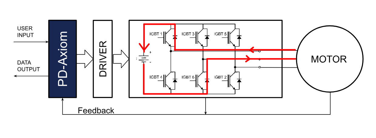
Only 1 phase is drawn for simplicity, but all 3 phases will contribute current.
That's an uncontrolled amount of current flowing to the battery, so a few things will happen:
- A large regen current will flow to the battery and the motor will act as a brake.
- If the powerstage can handle the current, great mechanical stress will happen with the possibility of losing the control of the vehicle.
- The current will flow into the battery for as long as the motor is above base speed, this could be milliseconds or several seconds, as its fueled by the inertia of the vehicle. Current could be well beyond 1kA, and the power dissipated by each body diode could reach several kW.
- If the powerstage can't take this amount of fault current, then the battery fuse or contactors should trip, and this unfolds another dangerous scenario: you are exchanging an uncontrolled current by an uncontrolled voltage. When the battery is disconnected it will no longer clamp the powerstage voltage and it will rise to whatever BEMF the motor is generating at that speed. Possibly destroying the inverter.
- Some applications allows a fault management that shorts the 3 motor phases if the load has a small inertia, probably not the case of an EV.
So back to our example of 10000 rpm base speed at 50V battery, which is typical for a small e-bike VESC, and you get a fault at 14000 rpm that halts your pwm. If your fault current is high enough to blow the fuse, you will have 140% of your battery voltage, that's 70V.
The problem is, those small VESC have an absolute maximum rating of 60V, so you will instantly blow your drive with big fireworks fueled by the vehicle inertia.
With an Axiom drive, the same principles apply, but since we use industry standard IGBT packages, if you have a 450V battery and you need FW to reach the speed equivalent to 800V, you have the possibility of swapping our recommended 650V IGBT for a 1200V part, thus allowing you to safely open the battery contactor the instant a fault is detected without causing damage and without the sudden and hard motor brake.
There are many ways to distribute the energy surge in a FW situation, we could explore them in a future log.
Unlike past logs, this feature has not been merged yet, and since its a critical and dangerous feature we are having some discussion before the PR is ready to merge, so stay tuned!
Discussions
Become a Hackaday.io Member
Create an account to leave a comment. Already have an account? Log In.