 Scott Swaaley
Now that you understand the DC power requirements from our previous post, it's time to get into the details. Let's start by looking at the typical specs for an AC/DC supply (listed below). Now, we get to start crossing off ones we don't care about.
- Input Voltage (AC): 120VAC
- Max Output Voltage (DC): 90V
- Output Power: 5kW
Output CurrentEfficiencyLine RegulationLoad RegulationRipple & Noise
So basically, we don't give two shits about most of the qualities that make a DC supply a "good" supply. This is a lucky break because finding affordable output caps in the milliFarad range rated for 100V is next to impossible. We're just pumping juice into a huge inductor (the motor) so we get to do it dirty. So if we remove all those unnecessary features of a DC supply ... what's left? In the simplest form, you have a half-wave rectified AC signal like the one shown below with an average "DC" voltage of 54V, a rms voltage of 85V, and a ripple voltage of 170V. That's pretty darn close to the 90V output we need. Let's try it.
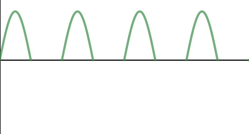
So something weird happened. I did the first test with a phase-chopped waveform to limit voltage (more later on this). Let's start with looking at the output voltage waveform of our half-wave rectifier.
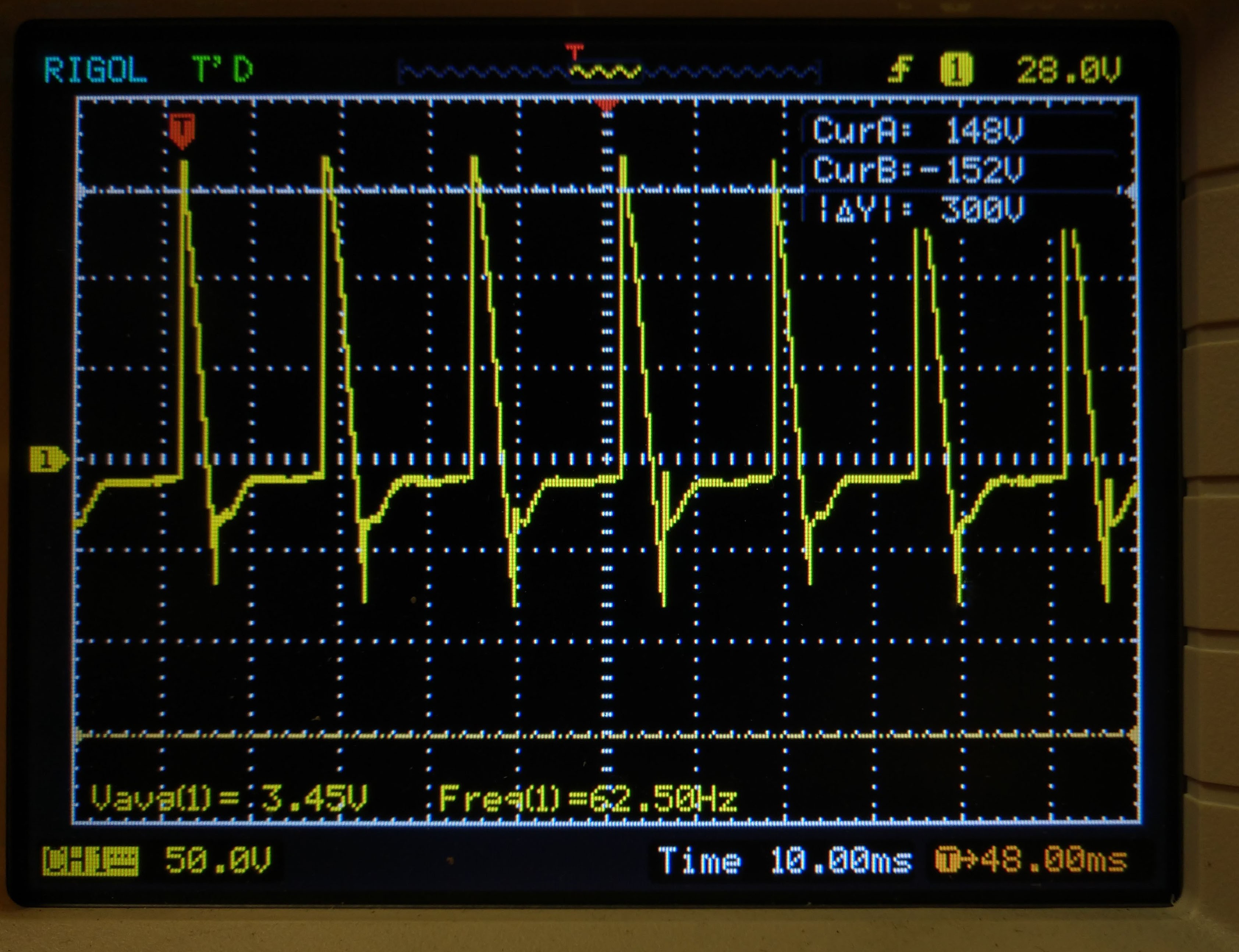
The strange thing is that when the output voltage should be zero (between positive ac waveforms), it goes negative as the magicnetics of the motor feed back into the supply. While this is happening, the motor continues to run at full speed (though sounding funny). Definitely not an effective braking means, even though it is "DC". What I think is happening is that the inductance of the motor wants the current to continue (as inductors like to do) so it creates a reverse voltage (the initial spike). This initial spike then discharges over the half cycle until it gets voltage again on the subsequent half wave. Without an actively-supplied current to force that missing half-wave into positive (and thus brake the motor) - it doesn't work. Lesson learned. You might be thinking that we should just use smoothing capacitors. We did the math and simulations and the capacitance (and voltage tolerances) would be HUGE to source energy for the 8ms between half-wave pulses!
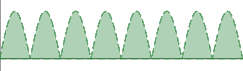
Next up is trying full wave rectification. The numbers for full-wave are a little scary, with an rms voltage of (not surprisingly) 120VDC. Added to that is the fact that when the motor sees "DC", it's overall impedance is MUCH lower and it draws much more current. We want to stop the motor slowly, not rip the shaft in half. We have some ideas to deal with this - more soon.
Discussions
Become a Hackaday.io Member
Create an account to leave a comment. Already have an account? Log In.