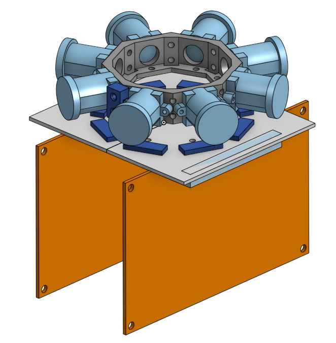
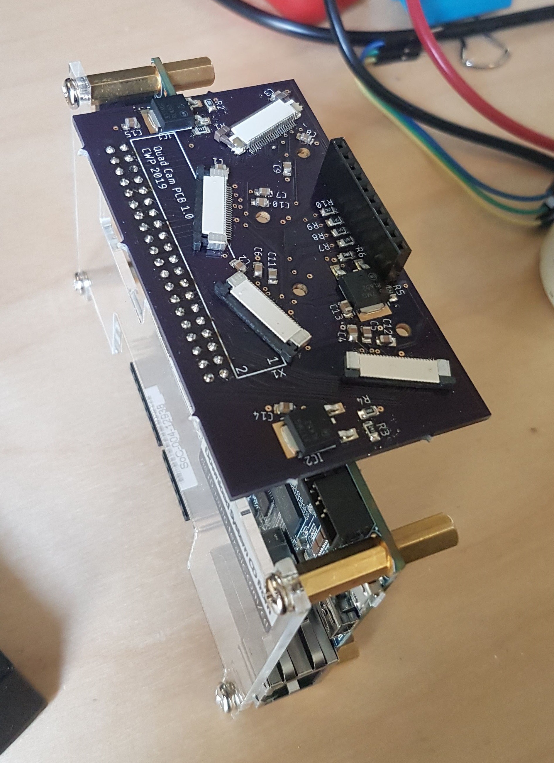
The camera interface PCB connects the DE10-Nano GPIO to 4 AR0330 modules and provides the power rails for the image sensors. My main design objectives were to keep the connections between the cameras and DE10 as short as possible to maintain signal integrity, and to mount the PCB perpendicular to the DE10 PCB so it would stay out of the cameras' field of view as much as possible.
To create seamless stereoscopic images, the 8 camera modules have to be laid out in an octagon with 64mm between every other camera's center of projection. I used OnShape to design a camera mount and sketch a PCB to attach to the mount and connect to the cameras. You can access the OnShape document here.
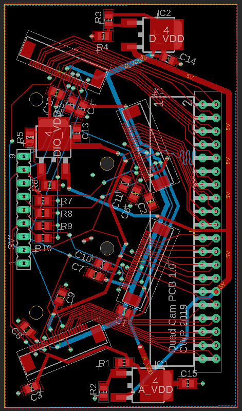
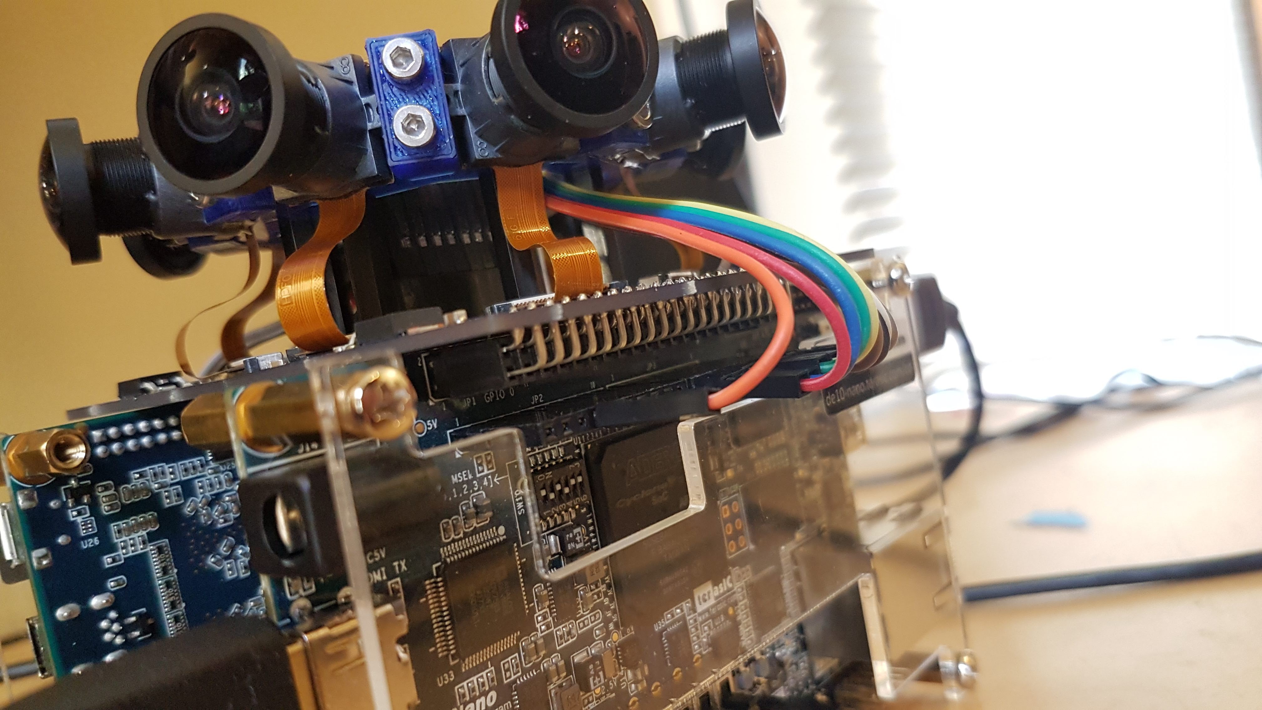
From OnShape, I exported the PCB shape, mounting hole locations, and connector positions as a DXF for use in Eagle. Ideally, I could route all of the camera connections through the 40-pin right-angle header and have only one connector to the FPGA board. Unfortunately, there are 36 available pins (4 for power and ground) and 4 cameras, leaving only 9 pins per camera. The parallel bus on each camera has an HSYNC, VSYNC, PCLK, and 10 pixel data lines. PCLK and HSYNC are the most critical to getting valid pixel data, so I opted to put these on the main header along with 7 bits of pixel data. 7 bits is far from optimal but the colors are going to be converted to 16-bit RGB with 5 bits per color so I don't think it makes much of a difference. The rest of the connections, VSYNC, XCLK (camera clock input), SDA, SCL, and RESET, are all on another header that connects via jumper wires to the DE10-Nano Arduino IOs.
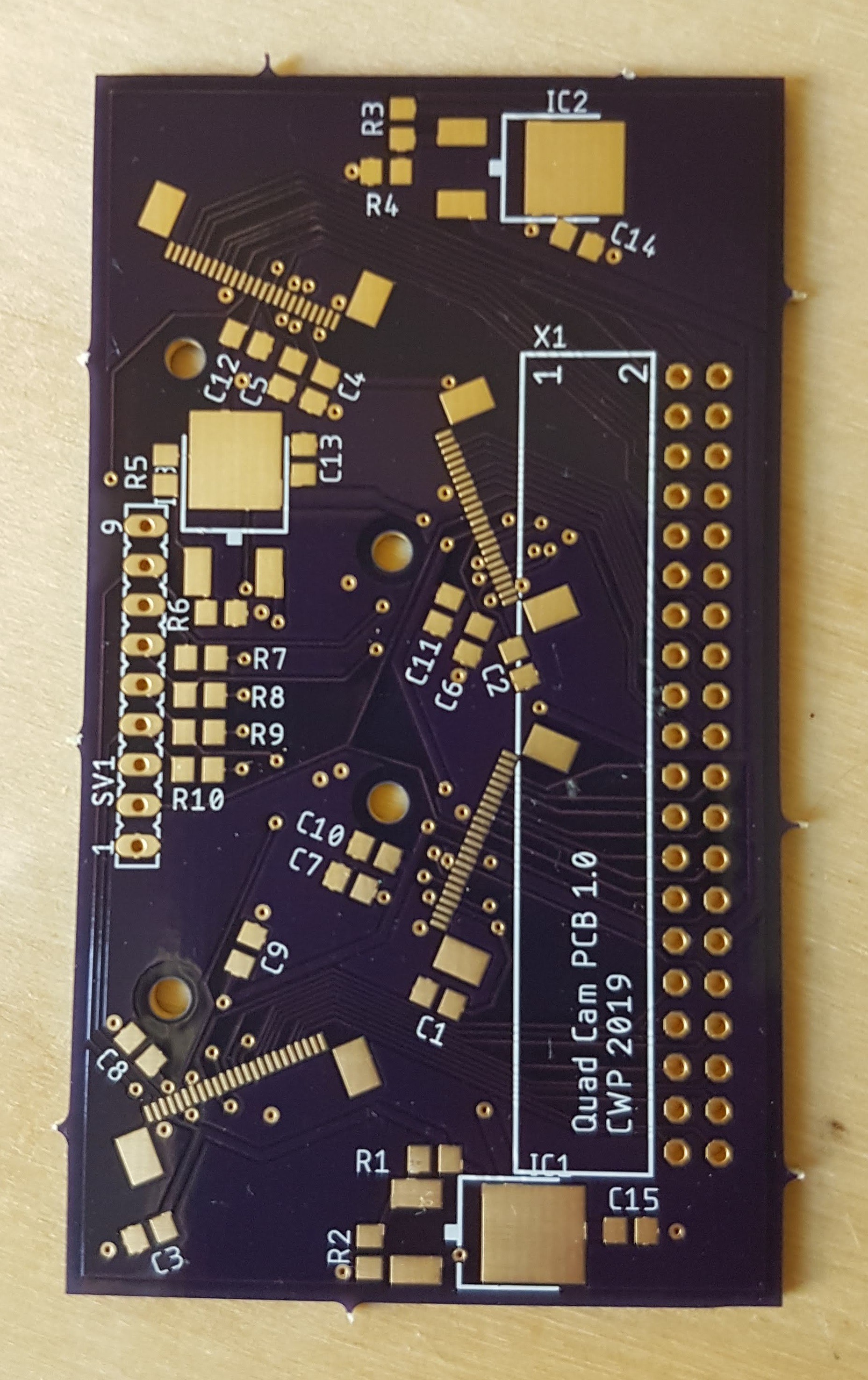
I ended up assembling the PCB using solder paste and a hot plate for the SMD parts. The camera connectors were surprisingly easy, requiring a bit of rework but a lot less than I experienced the last time I soldered this type of connector.
Check out the Files section of this project for the PCB EAGLE project and BOM.
Discussions
Become a Hackaday.io Member
Create an account to leave a comment. Already have an account? Log In.