The previous project log covered updates to the electrode signal modulation which seems to enable cutting without needing a very light touch onto the PCB surface. We expect that to make CNC cutting much easier. To find out, I brought back out the 3D printer base. It is a RAMPS/Arduino Mega based system, making it super easy to write some firmware to test this out. The first task was to create a keyboard remote controller interface for the CNC. I would use the WASD keys for x/y motion and RF for z motion. These commands would be sent over serial and the system would move the electrode accordingly. This worked really well. The video below shows cutting some shapes using this manually controlled CNC framework. It moves with XY steps of 5mm and Z steps of 0.5mm. At one point in the video, the cutting stops, I lower it 0.5mm, and it continues to cut. I did not have to be careful not to push too hard.
After that success, the next task was to try to cut a real example circuit, moving from an gerber file from EAGLE, to Gcode, to a cut PCB. I designed this useless PCB really quickly. It doesn't do anything, but has a few components which are of interest, such as 0805 and 1206 packages, a SOIC-8 package, a 10mil trace, and some through-hole components. More importantly, there is nowhere in the cut where the EDM continuity should be cut off, so this shouldn't need careful cut ordering.
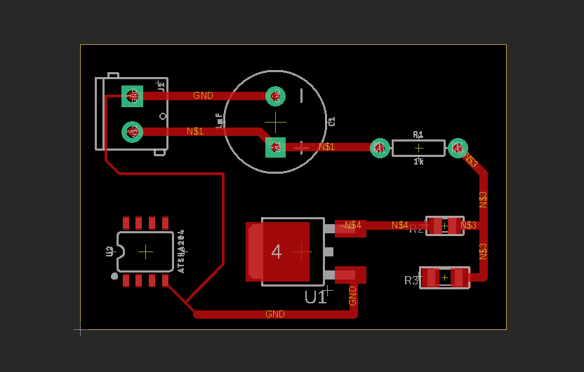
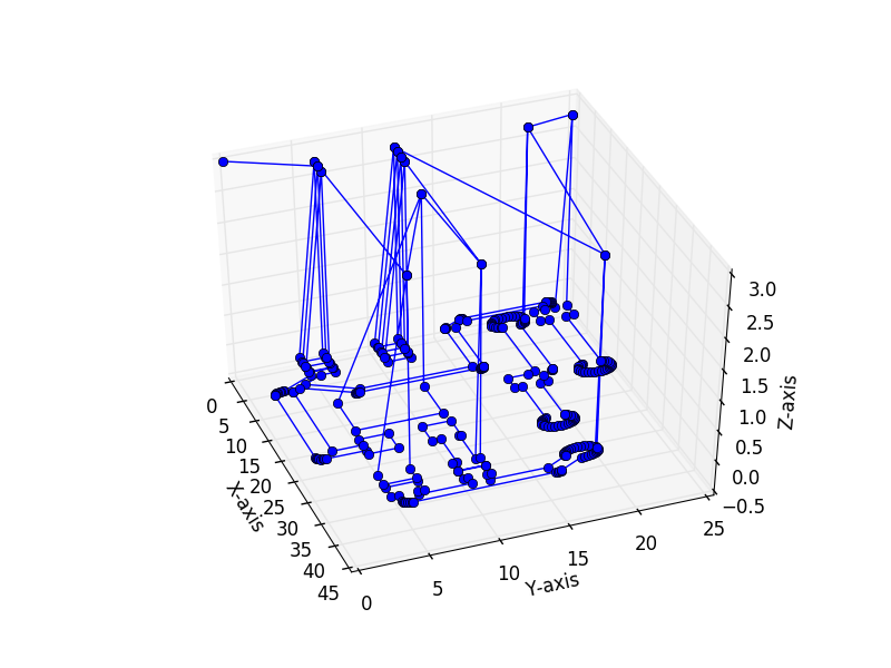
I have played with FlatCAM in the past for generating toolpaths for PCB milling, and was impressed by it. However, I was having some trouble installing it this time. I therefore tried using the online tool Carbide Copper. It seemed to work well enough for my needs, although FlatCAM has far more options, including tool size which is important here. Thankfully, Copper does not use Gcode arc commands, which I do not have supported yet (see below). Through curves it simply has more short motion commands. The image below shows the entire toolpath for this design.
Alongside this, I needed a Gcode interpreter. There are numerous options out there, but the ones I found seemed to be tied into other firmware pretty tightly. I'm sure there are other options and I'd love to hear about one if you know of one. However, as a quick test, I wrote my own which only handles a few commands. That said, the only command I should need for now is something like:
"G1 X0.453 Y-32.426 Z-0.100"
So this is what my interpreter looks for. It can also handle commands for absolute vs. incremental movement and for inches vs. mm units, as well as set home and go home commands. The Copper software outputs gcode a bit differently, so I hand wrangled it into this form for now. I could build a tool to do that automatically, or better yet use a proper gcode interpreter.
A python script reads each line of the gcode file, sends it over serial to the Arduino, which acts upon it, and then sends a special character ('*') once the motion is done. The python script then sends the next command. I tested this setup in open space first to make sure it doesn't do something stupid. Note I had also changed the mechanical interface slightly, moving the mechanical pencil tip used to guide the graphite to the bottom of the acrylic structure. This allows cutting motion to proceed without hitting the sides of the water tub. The gcode interpreter worked well. I was concerned about it having jerky motion since it waits until each command is complete before it receives the next one, but the motion looks fine.
Next, I need to put it all together and hopefully cut the very first full proof of concept PCB, and that is really exciting. Unfortunately, the capacitor bank is not charging currently, so hopefully I didn't burn something out. More to come...
Discussions
Become a Hackaday.io Member
Create an account to leave a comment. Already have an account? Log In.