Robert Hart
-
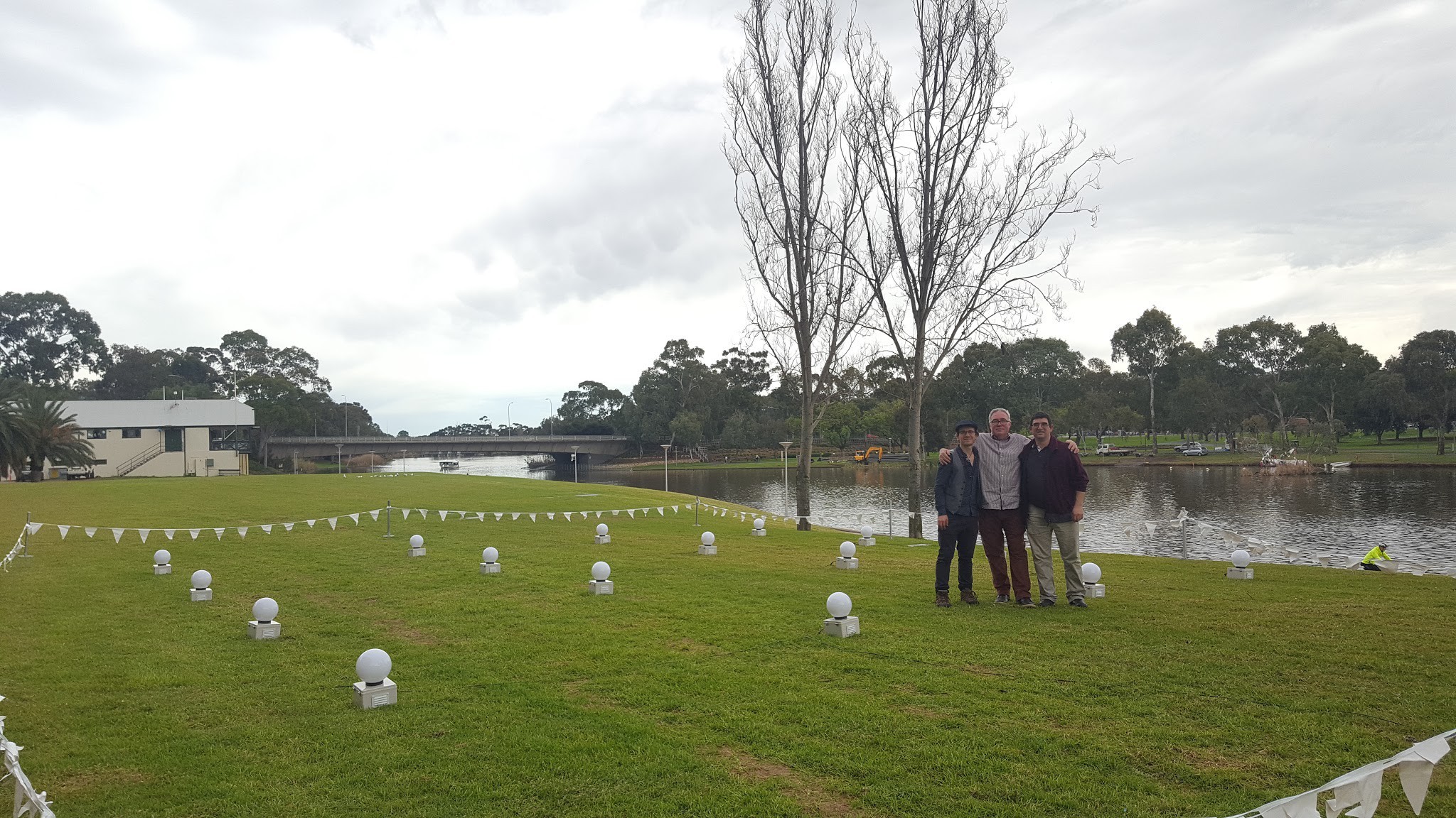
Cosmic Array goes Live
09/02/2017 at 08:01 • 0 commentsCollaborators
![]()
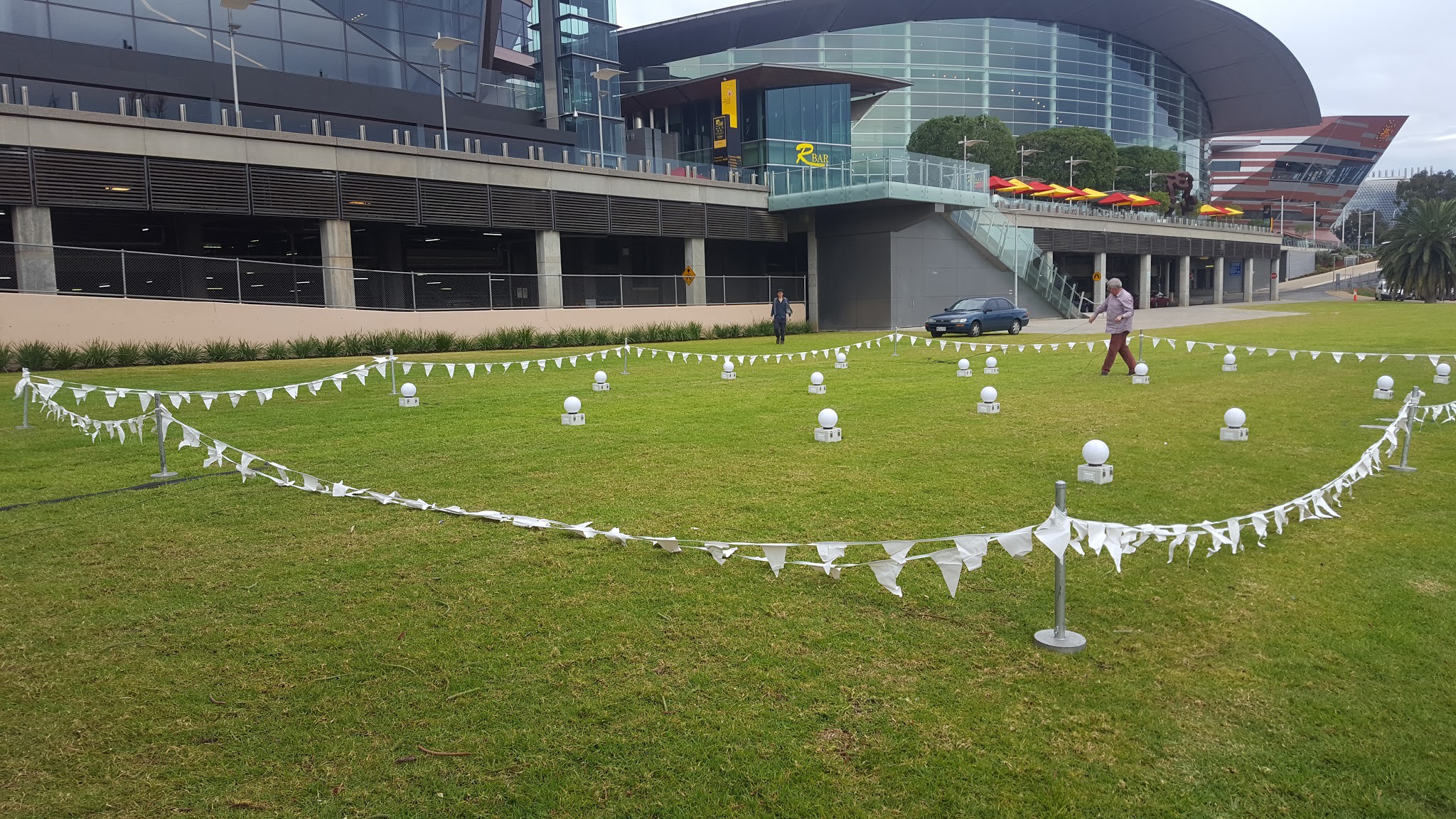
Cosmic Array Layout
![]()
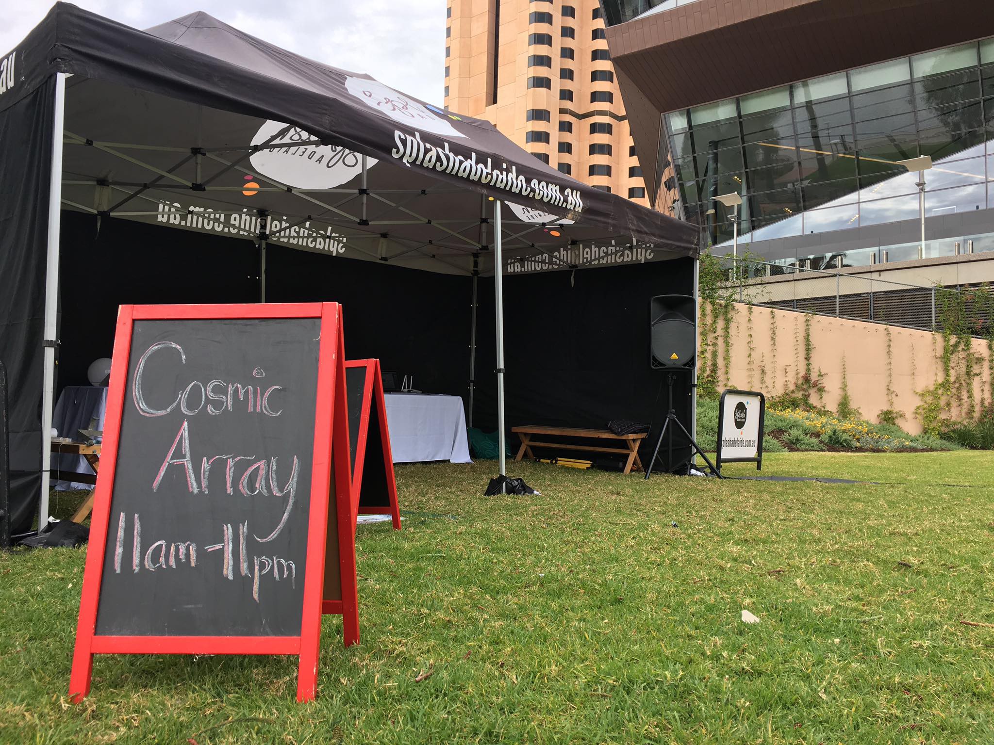
Tent for Infrastructure, Visitors and Cosmic Array Information
![]()
See videos:
-
First build of 16 element array.
09/01/2017 at 13:25 • 0 commentsThe last 2 months I have been preparing for my first demonstration project with an installation of an array of 16 detectors in Adelaide Elder Park, South Australia as part of the Winter Splash Adelaide. It was a lot more work than I expected, but I'm pleased to report it has been successful. It will be installed on the 2/9/2017. More to report soon. Here is a video of the build process from prototype to completed units tested in my back yard. The sound of the detectors will be recorded at the event soon.
-
SD Cards configured
07/30/2017 at 05:41 • 0 commentsThe software for the detectors has been installed on the SD Cards, and prepared for posting to Robert for installation in the Raspberry Pi Zero's.
This installation contains new audio files.

Some details
The OS Image being used is Raspbian Jessie (2017-07-05-raspbian-jessie-lite).
A Raspberry Pi 3 is used as it provides a wired network interface, as well as a screen and keyboard.
Once the OS Image has been written to the SD Card (16GB), it is booted with screen and keyboard attached and via the configuration tool (raspi-config), the hostname is set (cosmic-array-*-*), the SSH service is enabled and the Pi is rebooted.
SSH keys are manually copied to the card using ssh-copy-id.
An ansible playbook is used to connect to the system via SSH and setup the wireless, additional packages and to checkout the cosmic-array software from GitHub. While this might be slightly overkill for individual cards, these configuration tools will allow all 16 detectors to be modified and updated easily later on.
Finally, the 'config/install.sh' script is run from the cosmic-array software to setup boot parameters (audio system overlay), programs started on boot and audio volume settings. This script will probably be included in the ansible setup process in the future.
-
Code now available on GitHub
07/28/2017 at 11:04 • 0 commentsThe code, data and files required to drive the RaspberryPi Zero has now been made available via GitHub.
See: https://github.com/PaulSchulz/cosmic-array
This code is 'feature complete' for the standalone cosmic array sensor.
Suggestion, Comments, Branching and Patches welcome. Distributed under GPL v3.
-
Big problem solved with small fix
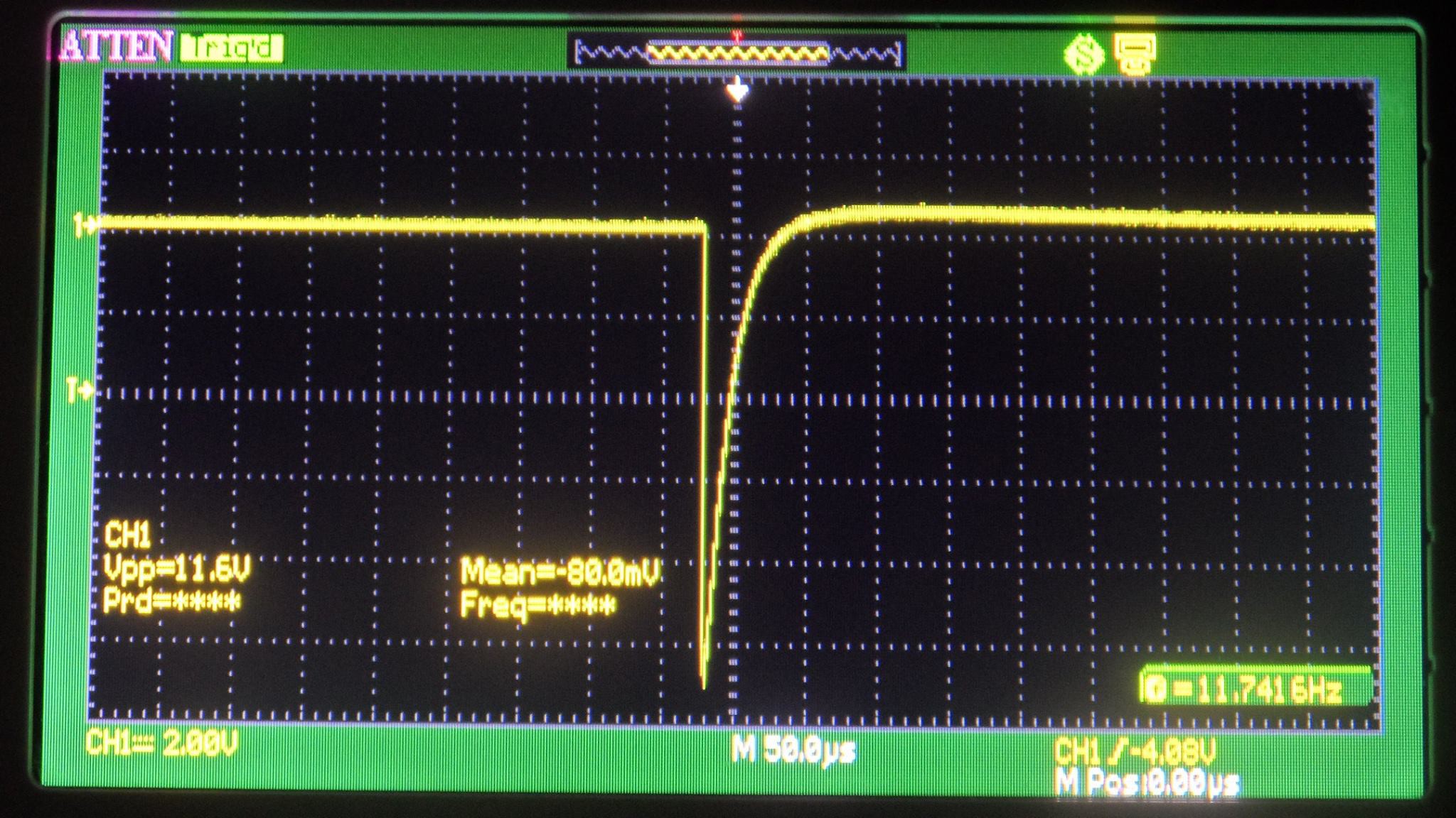
07/23/2017 at 11:35 • 0 commentsRecently we completed work on Cosmic Array sound and IoT using the new Raspberry Pi Zero W. But the addition of a Raspberry Pi and the audio amplifier caused the detector to trigger more often than it should. At first, it didn't seem to be an extra load on the 5V regulator. Nor the Geiger-Muller tubes after a check with a radioactive check source and DSO.
![]()
Then I remembered! I cut back on components to simplified the circuit design and cut costs. One of the components I removed was a 4V7 Zener diode on the output of the 10pf coupling capacitor connecting the Geiger-Muller tube to the 555 monostable oscillator trigger pin 2. At the time of the redesign, I forgot the real reason for the Zener just assuming it was there for voltage protection between the high voltage and low voltage sections.
The 555 timer acts as both a Schmitt trigger to shape the negative pulse from Geiger-Muller tube to a +5VTTL and increases the pulse width. Pin 2 of the 555 is the trigger for the monostable oscillator when it detects ground travelling pulse. So Pin2 is held at the supply rail voltage by a 47k resistor so when the high impedance negative pulse from the Geiger-Muller tube it triggers.
The trouble came when both the Raspberry Pi and the audio amplifier where added to the 5V supply rail that supplies the 555 circuits. Although the quiescent state supply rail measured 5V after coincidence is detected, the Pi plays a wave file and then the Audio amplifier causes ripple currents the trigger the other 555 monostable oscillators causing them to trigger randomly resulting in more ripple currents.
The solution is to hold pin 2 at 4.7V with a Zener diode and the problem goes away. The new boards are also designed with a higher current regulator further reducing this effect.
![]()
-
Cosmic Array and the Raspberry Pi Zero W
07/21/2017 at 08:45 • 0 commentsTo give each element of the Cosmic Array sound and IoT we are using the new Raspberry Pi Zero W.
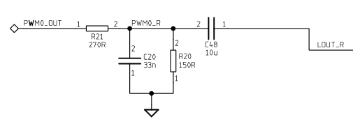
The Raspberry Pi Zero W doesn't have sound but with the addition of a low pass filter thanks to information on Adafruit Learn Blog this was quite straight forward.
![]()
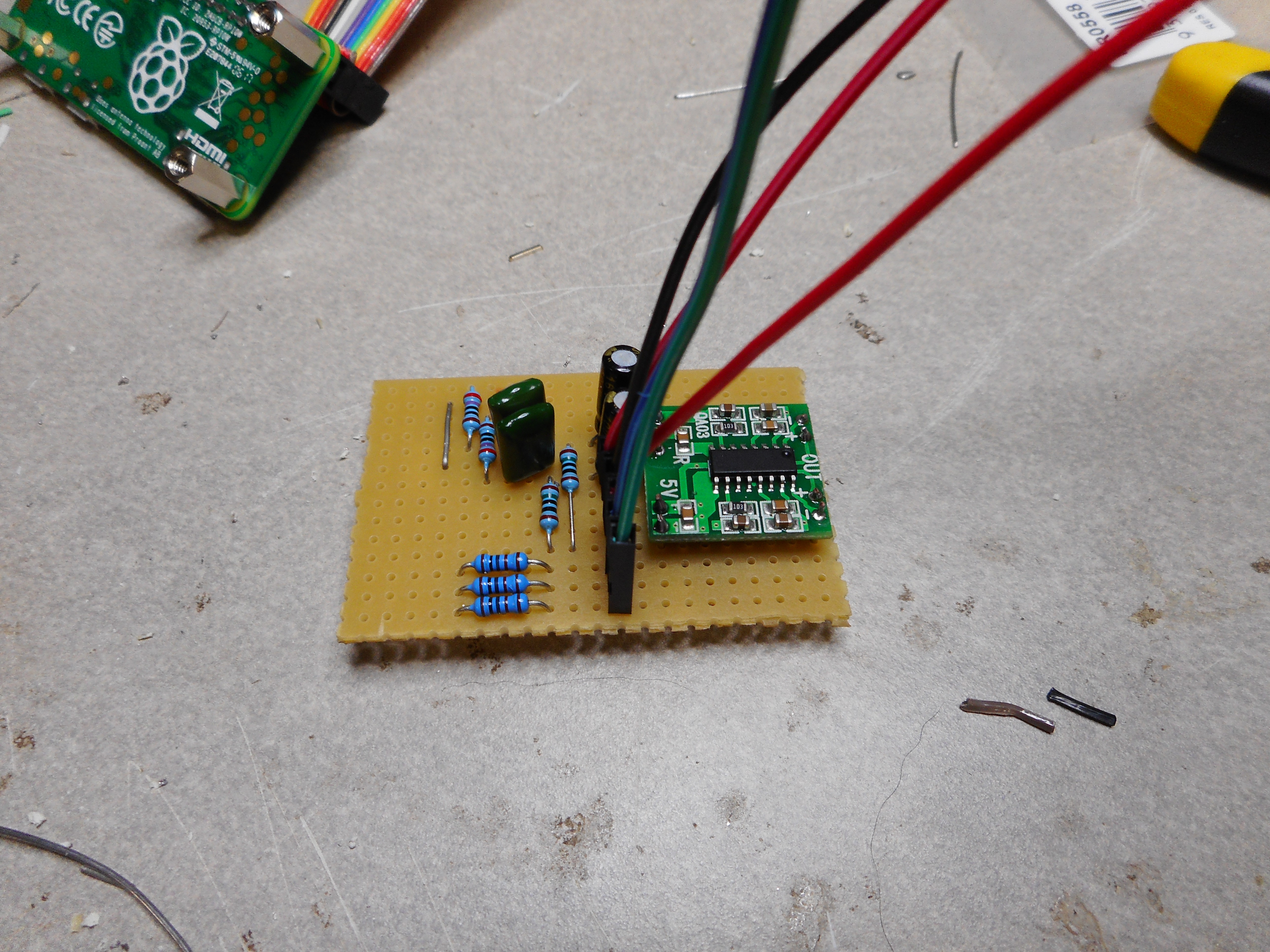
Amplified by a 5V 3W Class D amplifier based in the PAM8403 which is cheaper to source as a fully assembled PCB than a chip on its own.
![]()
![]()
![]()
I needed 16 4 x 4 Raspberry Pi Zero W for an Art installation at Splash Adelaide and although there has been a one order per customer limit imposed by the Raspberry Pi Foundation on suppliers.
Thanks to wonderful local Hackerspace Adelaide community we have been able to source 16 x Raspberry Pi Zero W for the task.
-
Final shape of the detectors coming togeter
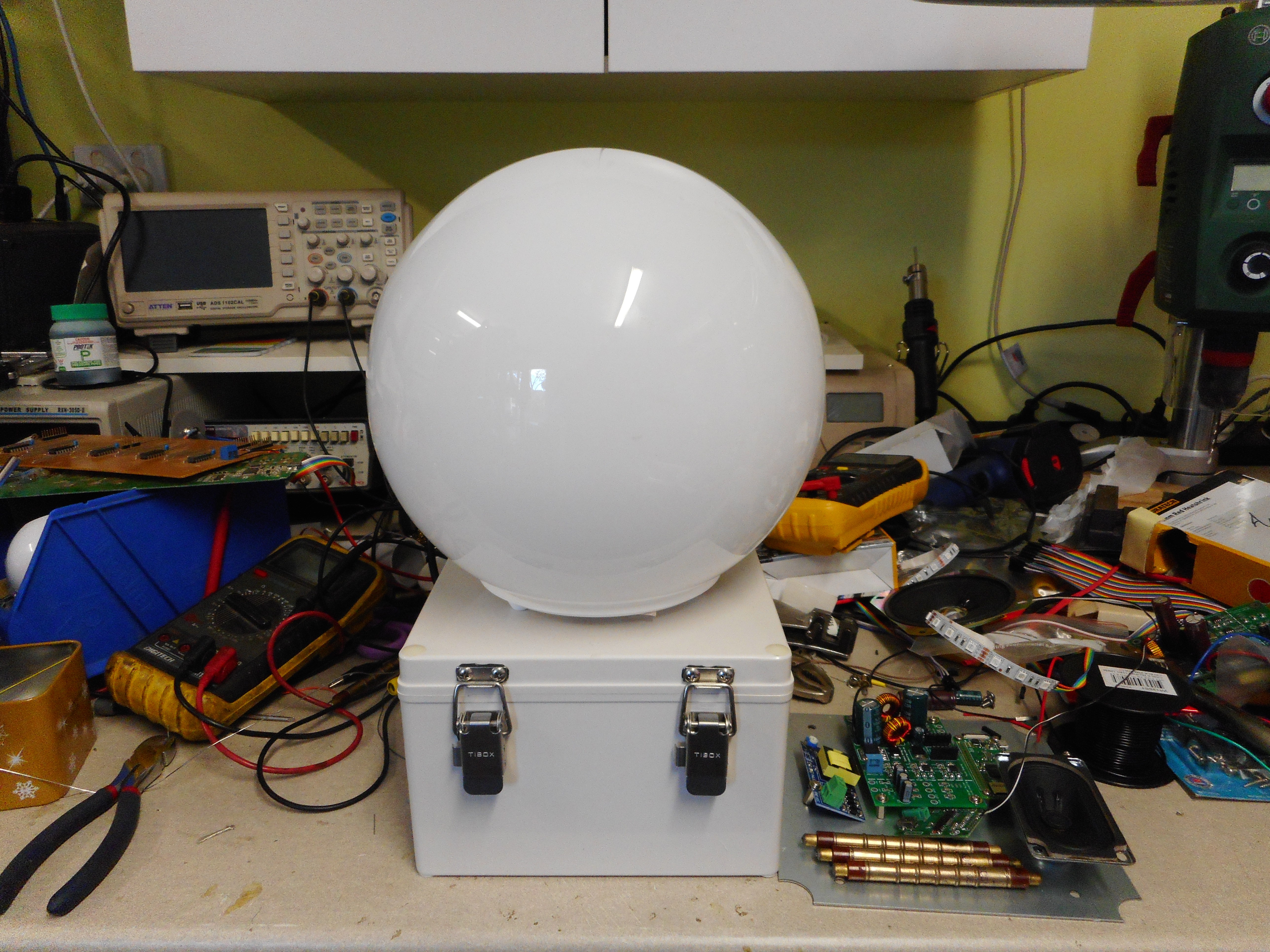
07/15/2017 at 00:05 • 0 commentsThe last few weeks while Paul has been developing the code for the Pi Zero W we'll be using in this build for IoT networking and sound effects. I've been working on the hardware and ordering parts for 16 detectors. As the detectors will be out in the weather they will need to be waterproof and have the ability add other features at a latter stage.
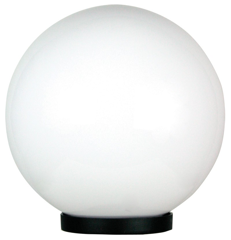
The unit will be slightly different to this as I've found a supplier of Outdoor UV resistant Acrylic Spheres.![]()
The spheres I will be using are on order and should arrive in a few days along with the waterproof enclosures both I've been able to source at wholesale.
![]()
Post Top Light Exterior Opal Acrylic Sphere E27 in 20cm Galactic Oriel Lighting. Exterior IP44 spherical opal acrylic post top. Complete with black polycarbonate base to suit 60mm outside diameter post.
![]()
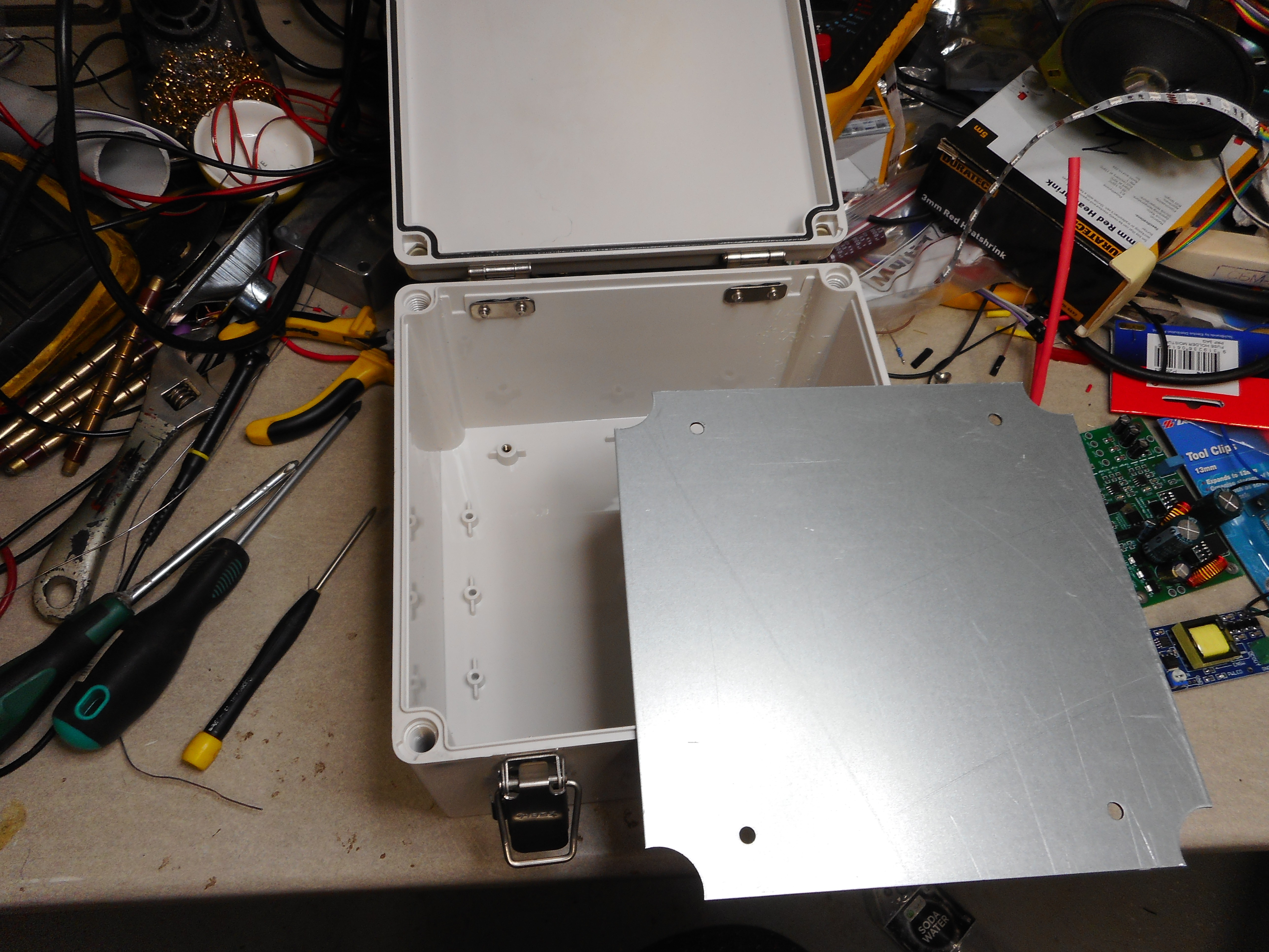
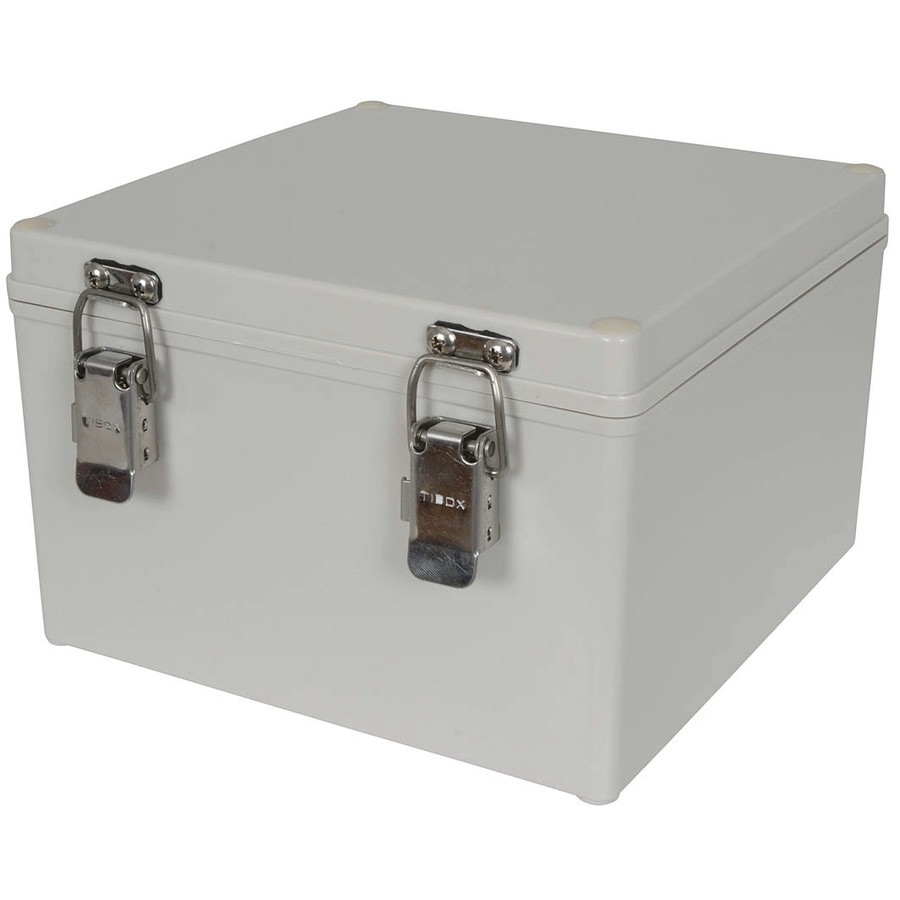
Gasket seals, stainless steel hardware and IP66 rated , Opaque cover: 200(L) x 200(W) x 130(D)mm, ncludes a 1.8mm galvanised chassis for mounting electronics.
![]()
![]()
-
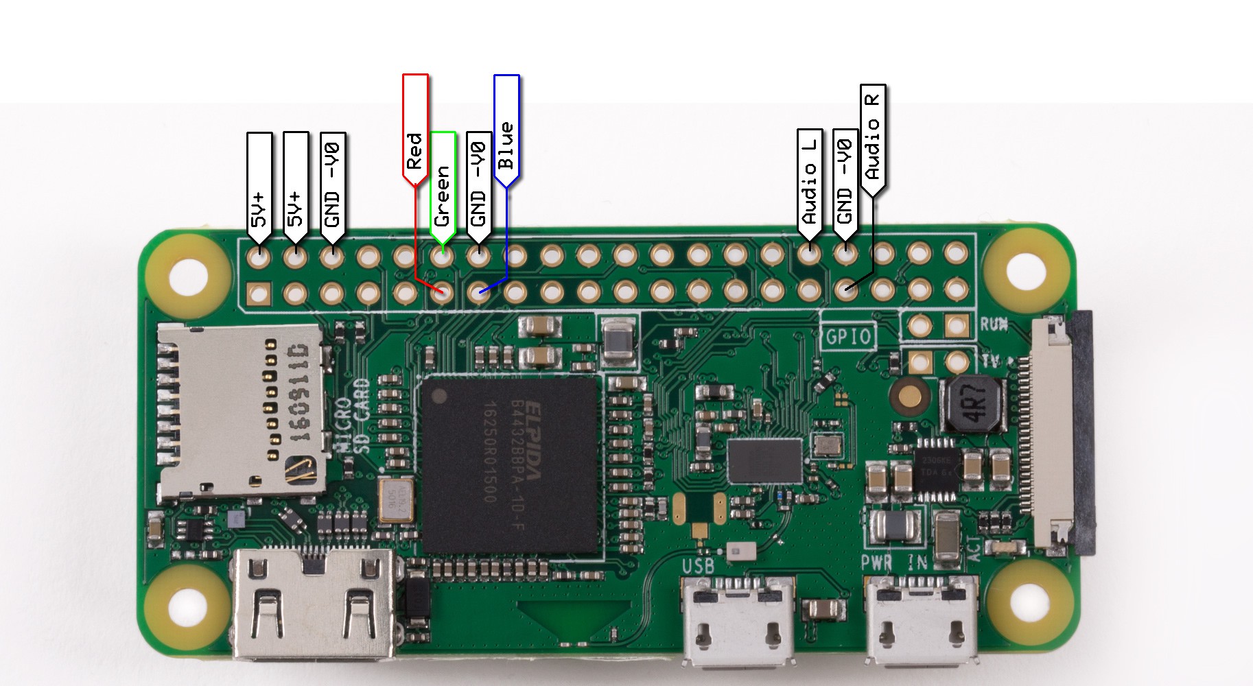
Raspberry Pi Pinouts
07/13/2017 at 00:36 • 0 commentsThe following are the proposed pinout allocations for the Raspberry Pi (Pi 3 or Pi Zero W) in the project.
 +--------------+---------+---------+----------+---------+---------+--------------+
 | Description  |    Name |    Mode | Physical | Mode    | Name    | Description  |
 | (Connected)  |         |         |          |         |         | (Connected)  |
 +--------------+---------+---------+----++----+---------+---------+--------------+
 |              |    3.3v |    3.3v |  1 || 2  | 5v      | 5v      | +5v Supply   |
 |              |   SDA.1 |       - |  3 || 4  | 5v      | 5v      | +5v Supply   |
 |              |   SCL.1 |       - |  5 || 6  | GND     | 0v      | Gnd Supply   |
 |              | GPIO. 7 |       - |  7 || 8  | -       | TxD     |              |
 | Logic Gnd    |      0v |     GND |  9 || 10 | -       | RxD     |              |
 | Chan. Red    | GPIO. 0 |  IN/TRI | 11 || 12 | IN/TRI  | GPIO. 1 | Chan. Green  |
 | Chan. Blue   | GPIO. 2 |  IN/TRI | 13 || 14 | GND     | 0v      |              |
 |              | GPIO. 3 |       - | 15 || 16 | -       | GPIO. 4 |              |
 |              |    3.3v |    3.3v | 17 || 18 | -       | GPIO. 5 |              |
 |              |    MOSI |       - | 19 || 20 | GND     | 0v      |              |
 |              |    MISO |       - | 21 || 22 | -       | GPIO. 6 |              |
 |              |    SCLK |       - | 23 || 24 | -       | CE0     |              |
 |              |      0v |     GND | 25 || 26 | -       | CE1     |              |
 |              |   SDA.0 |       - | 27 || 28 | -       | SCL.0   |              |
 |              | GPIO.21 |       - | 29 || 30 | GND     | 0v      |              |
 |              | GPIO.22 |       - | 31 || 32 | OUT/PWM | GPIO.26 | Audio Out(L) |
 | Audio Out(R) | GPIO.23 | OUT/PWM | 33 || 34 | GND     | 0v      | Audio Gnd?   |
 |              | GPIO.24 |       - | 35 || 36 | -       | GPIO.27 |              |
 |              | GPIO.25 |       - | 37 || 38 | -       | GPIO.28 |              |
 |              |      0v |     GND | 39 || 40 | -       | GPIO.29 |              |
 +--------------+---------+---------+----++----+---------+---------+--------------+
 | Description  |   Name  |    Mode | Physical | Mode    | Name    | Description  |
 +--------------+---------+---------+----------+---------+---------+--------------+
-
Event Capture and Recording with Raspberry Pi (Part 2b)
07/06/2017 at 08:48 • 0 commentsThis log entry follows on from Part 1, and Part 2a.
Transmitting Cosmic Array Detection Events
The RaspberryPi 3 (or RaspberryPi Zero W) receives events from the detector via the toggling of the General Purpose IO (GPIO) lines. These lines are monitored by software on the Pi, which registers interrupt functions for each line, which is called when an event is detected.
This means that the processor doesn't need to continually poll the GPIO lines for their state, saving processing time, and can also react immediately (interrupting whatever it was doing), improving reaction time.
The previous program written to send UDP event packets across the network (udpsend) has been changed to use interrupt functions. While doing this, it was discovered that the WiringPi library also allows multiple programs to be triggered by the same interrupts. This has proven useful for also getting the detector to produce sound effects (eg. play wav files) and the code for this is below:
/*
 * cosmicray-play.c - Play an audio file on a cosmicray event.
 * usage: cosmicray-play
 */
#include <stdio.h>
#include <stdlib.h>
#include <wiringpi.h>
/*  error - wrapper for perror */
void error(char *msg) {
  perror(msg);
  exit(0);
}
/* interrupt functions */
void my_interrupt(int i) {
  system("aplay audio/beep.wav > /dev/null 2>&1 &");
}
void my_interrupt_0 (void) { my_interrupt(0); }
void my_interrupt_1 (void) { my_interrupt(1); }
void my_interrupt_2 (void) { my_interrupt(2); }
void my_interrupt_3 (void) { my_interrupt(3); }
void my_interrupt_4 (void) { my_interrupt(4); }
void my_interrupt_5 (void) { my_interrupt(5); }
void my_interrupt_6 (void) { my_interrupt(6); }
void my_interrupt_7 (void) { my_interrupt(7); }
int main(int argc, char **argv) {
  wiringPiSetup();
  /* check command line arguments */
  if (argc != 1) {
    fprintf(stderr,"usage: %s\n", argv[0]);
    exit(0);
  }
  /* setup interrupt handlers */
  wiringPiISR (0, INT_EDGE_FALLING, &my_interrupt_0) ;
  wiringPiISR (1, INT_EDGE_FALLING, &my_interrupt_1) ;
  wiringPiISR (2, INT_EDGE_FALLING, &my_interrupt_2) ;
  wiringPiISR (3, INT_EDGE_FALLING, &my_interrupt_3) ;
  wiringPiISR (4, INT_EDGE_FALLING, &my_interrupt_4) ;
  wiringPiISR (5, INT_EDGE_FALLING, &my_interrupt_5) ;
  wiringPiISR (6, INT_EDGE_FALLING, &my_interrupt_6) ;
  wiringPiISR (7, INT_EDGE_FALLING, &my_interrupt_7) ;
  for(;;){
    delay(100);
  }
  return 0;
}
Can be compiled with:
gcc -o cosmicray-play cosmicray-play.c -lwiringPi
Then run it from a directory where a suitable 'wav' file is available.
Next time: Collecting and storing event data in a database (Part 3).
-
Event Capture and Recording with Raspberry Pi (Part 2a)
07/02/2017 at 14:33 • 0 commentsTransmitting Events over the Network
I thought that I would split this next series off log entries into short pieces that I can write up as they are completed.
Programs and code seen here will be made available via a Github repository in due course.
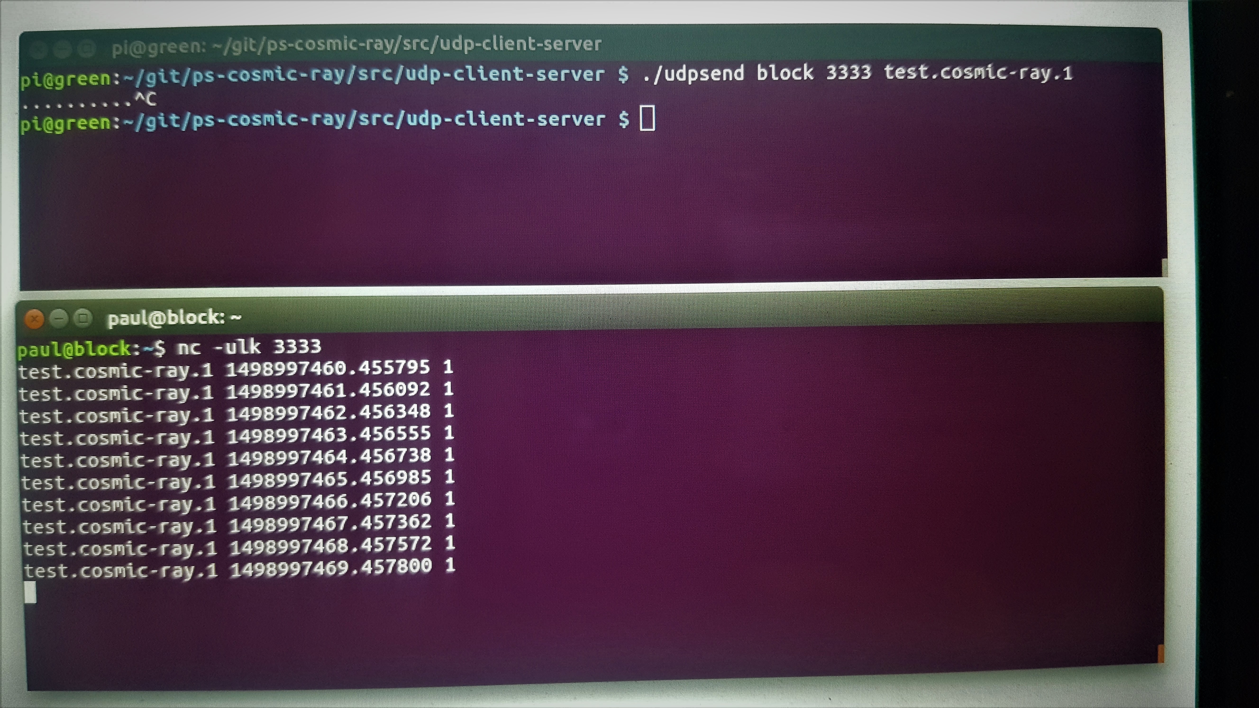
The following image shows the program on the Raspberry Pi3 (udpsend) transmitting data across the network to a server (called 'block') which is listening for the packets (on UDP port 333, via the netcat/nc program) and printing the data as it is received.
The udpsend program is currently sending one packet per second of test data. The next version will be triggered by a pulse on a GPIO line (see previous log entry) which will then transmit a packet with the details to a listening server.![]()
The choice to use UDP packets instead of TCP means that there is no additional overhead in the reception of data across the network, and also allows incoming data to be received form multiple sources.
Wifi and Ethernet collision detection, avoidance and re-transmission should handle the case of small cosmic ray detection cascades, The affect of congestion on packet loss when large numbers of detectors (100's) and events are present will need to be investigated in due course. In the first instance, It may be necessary to reduce the data sent in an event packet.
The next log entry in this series will discuss the capture and transmission of actual events from a single detector.
Cosmic Array
An array of cosmic ray detectors across a landscape that demonstrates in light and sound how cosmic rays are constantly all around us.