 Electro Guruji
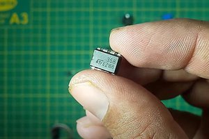
Learn how to make a precisely adjustable timer with a variable delay from 1 - 100 seconds that uses the 555 IC. The 555 timer is configured as a Monostable Multivibrator. The output load is driven by the relay switch which is in turn controlled by the timer circuit.
Since the project only involves assembling a simple circuit by following the schematic, it will only take an hour to make.
Don't forget to Subscribe for more projects: YouTube


 utsourceproduct
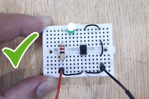
 UTSOURCE
 Kody Alan Rogers
 Chris
Chris