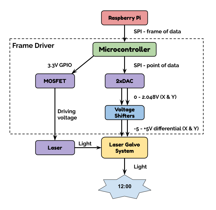
The purpose of the Frame Driver is to receive a "frame" of data from the Raspberry Pi and then output it until it receives a new frame. The Frame Driver will guide the laser beam around a path over the course of 1/30th or 1/50th of a second, turning the beam on and off as appropriate, and then do it, over and over again.
There are several steps between receiving a frame from the Pi, and outputting voltages to the Laser Galvos.

Microcontroller
I've decided to use a PIC32MX170F256B-50 microcontroller. There were several reasons:
- The PIC32 is big enough that things are easy. It's definitely possible to do this with a smaller controller - see cfavreau's Arduino-powered Open Laser Show DAC - but I didn't want this to be hard to program, and I have no intention of large-scale production. 50MHz, multiple SPI peripherals, 64k of RAM and 256k of flash is more than enough. Cheap 32 bit arithmetic will likely help, too.
- The PIC32 is a relatively simple, controllable processor. I will be able set timers and handle interrupts to microsecond accuracy. The problem with Raspberry Pis and BeagleBones in this application is that they multiplex so much that they are no longer able to faithfully handle strict timing requirements. Listening to Bart Dring on The Amp Hour #438 talking about the ESP32 GRBL interpreter, the ESP32 could probably handle the timing requirements, but it's not trivial.
- I've been wanting to learn PIC32 for a while now.
DAC
I chose MCP4822 dual 12-bit DAC. It has an internal 2.048 voltage reference and has an SPI interface.
In this post on laserpointerforums.com, the consensus seems to be that an 8-bit DAC is not sufficient, but that a 12-bit DAC is plenty. 12 bits gives 4096 steps, which would be somewhere between 0.2 and 0.4mm per step on my kitchen wall, which seems sufficient, especially given that the laser beam is 1-2mm mm wide. Beyond 12 bits, things start to get quite pricey, and there's little additional advantage in having 0.05mm precision over 0.2mm precision at normal view distances.
For the cheaper DACs, there are two common standards for loading data: I²C and SPI. Generally, SPI is a faster protocol, both in terms of physical link speed and in having a lower protocol overhead. The MCP4822 can transfer data with a 20MHz clock and I am expecting to be able to use at least 5MHz.
Outputting two values from the MCP4822 DAC requires two 16 bit SPI transfers and then setting the LDAC pin low. At 5MHz, this will take (16 * 0.2 * 2 + a bit)μs ~= 8μs, which is fast enough. The DAC requires a "typical" 4.5μs to change its output signal from one level to another, anyway.
To ensure that the internal voltage reference is stable, a very stable power supply is required.
Voltage Shifter
The final component in the Frame Driver is the voltage shifter which takes two single-ended 0-2.048V signals and amplifies them to the +/-10V differential signals (maximum magnitude of any given line is +/- 5V) expected by the Galvo controller boards. It will be composed of 4 op amps, in a single package. I chose the TL084, because cfavreau used it successfully in his Open Laser Show DAC. It's also the same part used on the Galvo driver boards.
Power
Finally here is how I plan to power each of the components:
| Component | What it Needs | How it Will Get it |
|---|---|---|
| PIC32 | 3.3V, < 100mA. | Pull from RPi 3.3V pins |
| MPC4822 | 3.3V, a few mA, low ripple | Dedicated 3.3V regulator running from from RPi 5V pins |
| TL084 | + and - 8V supplies, <20mA | Dedicated regulators running from Galvo +/-15V supply lines. |
 Alan Green
Discussions
Become a Hackaday.io Member
Create an account to leave a comment. Already have an account? Log In.