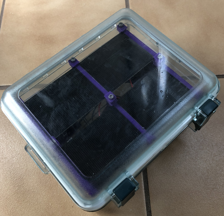
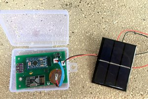
Here is the sensor in the waterproof enclosure:
Here is the sensor outside of the enclosure:
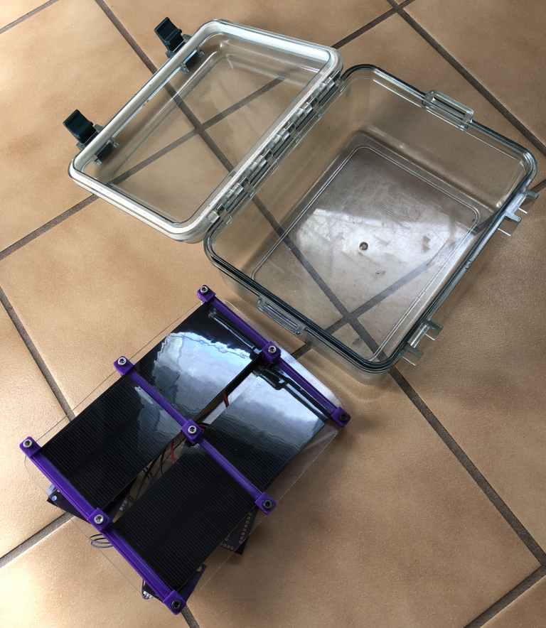
I 3D printed the solar panel holders and secured the panels to a piece of plastic from Home Depot.
Here is the backside of the solar array, with the custom made PCBs.
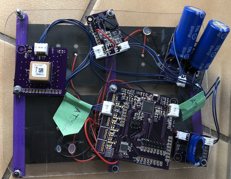
Why did I make a bunch of PCBs instead of one? It is easier to make the PCBs and test them individually, and the JST connectors don't add much to the cost. Plus, then the different parts can get reused later.
The input from the solar array can vary in voltage depending on the sun. The solar array is fed into a small conditioning circuit (schottky diode, capacitor, and zener diode) to aid and protect the circuits downstream (zener diode is 5.6 V, 3W).
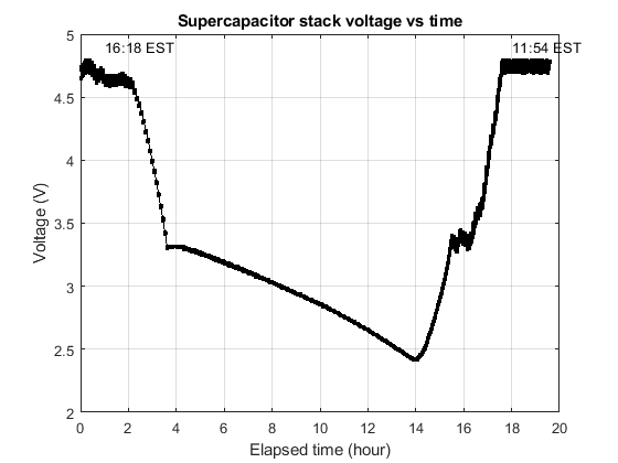
Next, the power is fed to the supercapacitor charger to charge up a couple of 50 F supercaps.
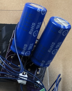
The supercapacitors can supply a tremendous amount of current, so the output is fused with a PTC fuse.
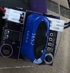
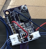
The output of the supercapacitors is fed to an energy harvesting DC/DC converter. This way, the supercapacitor voltage can vary from ~0.25 V to 5V, and the DC/DC converter will output 5V the whole time. Basically, you get the whole energy storage potential of the capacitors! Here is the DC/DC converter:
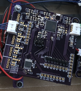
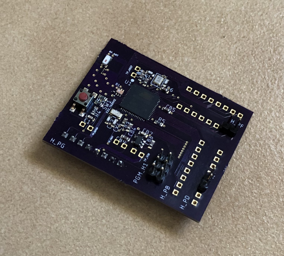
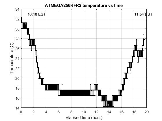
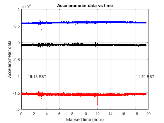
The stable 5V is sent to the ATMEGA256RFR2 board. The board has a SMD chip antenna, and a LSM303 (accelerometer and magnetometer). To power different accessories, there are 4 load switches that can enable/disable the 5V. There is also a UART multiplexer since the ATMEGA256RFR2 only has two UART ports.
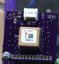
One accessory I made was a GPS using the SAM-M8Q-0-10.
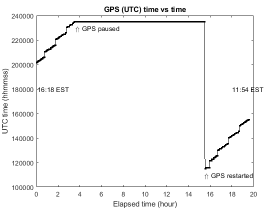
The ATMEGA256RFR2 was coded up using AtmelStudio. Every few seconds the watchdog timer wakes up the microcontroller. The magnetometer and accelerometer are read. The supercapacitor voltage is measured. If the voltage is really good, then the GPS is turned on and the location/UTC time is captured. If the supercapacitor voltage is good enough, then the ISM Tx is powered up, and the latest data is sent to the base station.
The base station is just another, simpler ATMEGA256RFR2 board that I made for testing.


 Gos
Gos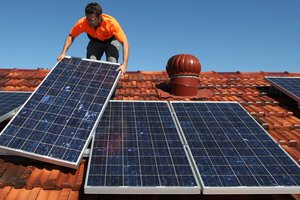
 andrew
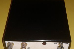
 Scott
Scott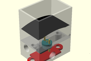
if there is any aspect of the design that you want more details about, please let me know. This way, I can prioritize the log entries and possible YouTube videos.