 Andy Geppert
In my previous work, the cores were starting to come alive and the LEDs were showing evidence of this. But only some cores worked, and they were not lined up with the LEDs they were supposed to affect. This was evidence of multiple problems.
I began to suspect whether the LED array functions were mapped correctly to the LED positions. Since that is independent of the cores, I set out to resolve that issue and I have completed the API that allows interaction with the LED array. I have included test functions to confirm it works in monochrome or color mode, and can be addressed as either a series of 64 LEDs, as a matrix by X/Y position, and as a 64-bit binary value (which makes it easier to visualize the bytes by rows if numerical data is to be stored). Turns out the LED addressing was correct, although the API clean-up was a huge improvement. So if the LED addressing was correct, that might mean the core addressing was not correct. And now the LED Array HAL is above the LED Driver, but that's another story.
Now back to the hardware. I discovered and fixed two errors in the core polarity change sensing circuit (used for reading the bits). The first mistake I made was swapping the inputs to one of the op-amps used to sense core pulses that occur when a core changes polarity. The second mistake was a poor choice to skip the use of an OR gate to combine the outputs of the two op-amps. Yes, that's just an outright fail on my part. The result of those mistakes were that the core polarity changes were *sometimes* working That made bring-up... challenging... Here's the repair work:
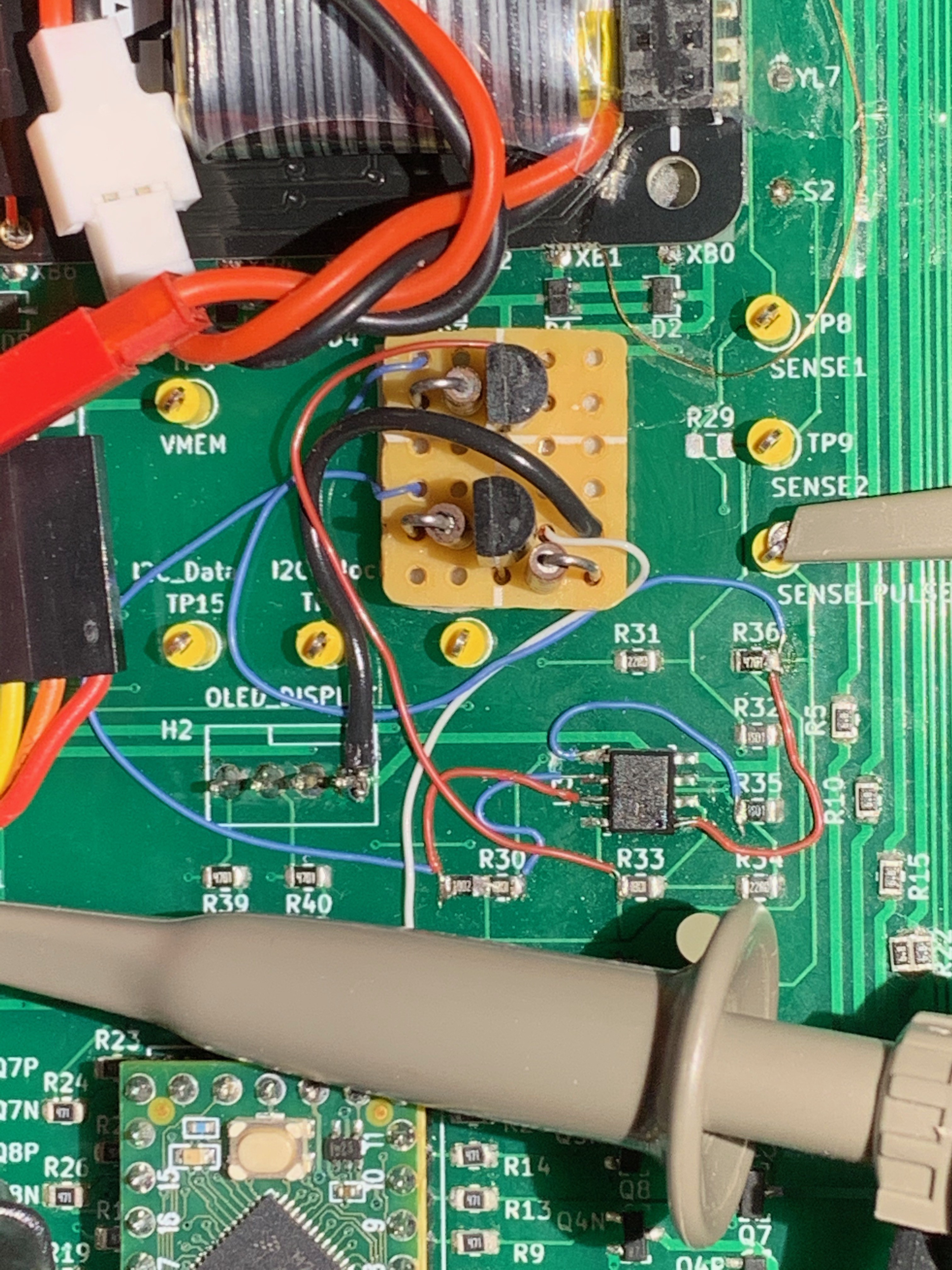
At least everything was well labeled so it was relatively easy to blue-wire the OR gate in. Now the core polarity sensing is working, so I moved on to determining if the cores are working.
Indeed, the cores are working!!! That was an exciting step. And, because I was previously swapping some current setting resistors, that explains why some of the cores work (with more current) and some don't. I'll calibrate the resistor selection later, but the more pressing problem now is that the transistor matrix addressing logic needs some work. I failed to account for the alternating arrangement of the cores. They are canted left then right, alternating through the rows and columns. This is to reduce the number of drive transistors required, but the result is that the linear addressing of all the bits in nice rows was wrong-headed. I re-discovered that the odd and even bits are in different rows. I knew this before because that is how Jussi's Core Memory Shield worked, and I had to understand that mapping to make the LEDs line up. Now that I've re-learned this fact, I am updating the row addressing logic into a bit more complicated look-up table. The first five bits are now confirmed working and in proper order, counting from 0 to 4 in the upper left of the array. I'll expand the look-up table accordingly, and that should resolve the positioning of all the cores to line up visually. And then I can tweak the current drive resistors and get all of the cores working reliably.
Overall, major progress! Won't be long and I'll be drawing directly in the core screen memory.
Discussions
Become a Hackaday.io Member
Create an account to leave a comment. Already have an account? Log In.