 Andy Geppert
The learning continues, and this time with some success to show for it!
Here are all 64 cores, each being written to with a 0 and then a 1.
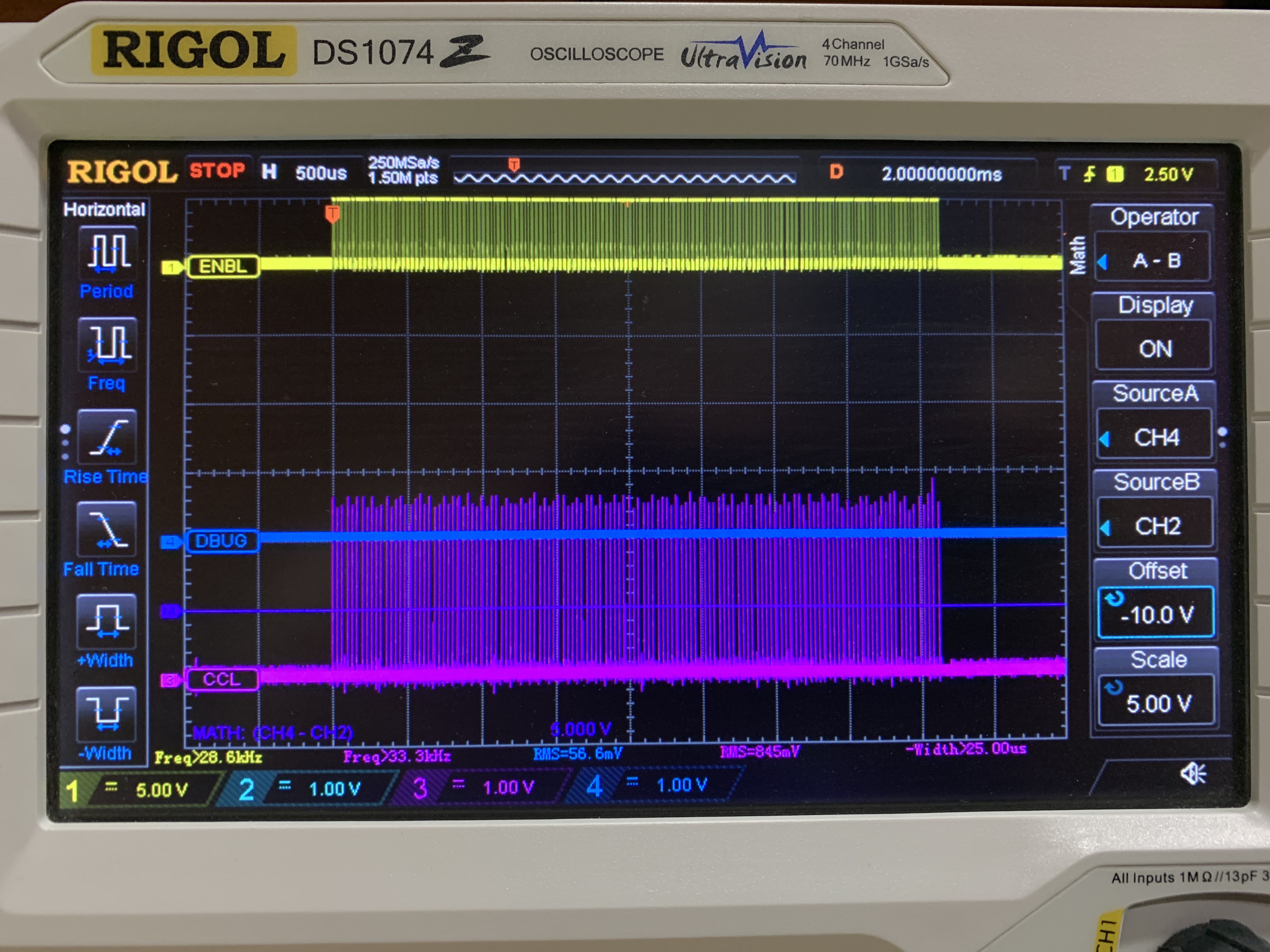
Yellow trace is the ENABLE during each write, and the purple trace is the sense wire pulse that indicates the core changed polarity.
In the last update I grafted in an OR gate and corrected a +/- swap on one of the Op-Amps. That brought the sense circuit to life. But there was much more ground to cover. Here are the ugly details.
1) The cores were not behaving in the right arrangement with the LEDs. The fix was to map the electromagnetic core addressing to the physical layout of the array. In the standard core array design I am using, in order to keep the component count minimized, the cores are placed in an alternating sequence. In other words they cant left, then right, then left, and so on. If one ignores that fact, the consequence is that writing a 1 to bit 0 is in the first column of the first row, and then bit 1 is on the 2nd column... but on the fourth row. I implemented a look-up table array to get them all in order. This is important because I am physically mapping the cores as screen memory to the LED array directly underneath. They must line up.
2) Then I found that some cores worked, and some didn't. Sometimes the first four in a row, sometimes a whole row. In some rows, nothing worked. Is it a coding problem? Another circuit design problem? Bad components? Assembly error? All of the above?
3) The first row wire was intermittent. Cold solder joint. Easy fix.
4) Awhile back, in an effort to get things working, I made the mistake of trying out FETs instead of transistors. I was looking to drive more current in the core matrix wires. If you drop FETs into a circuit designed for transistors, without the additional components that make FETs work correctly... you get something that kinda works. The signals to the gates look, um, not square:
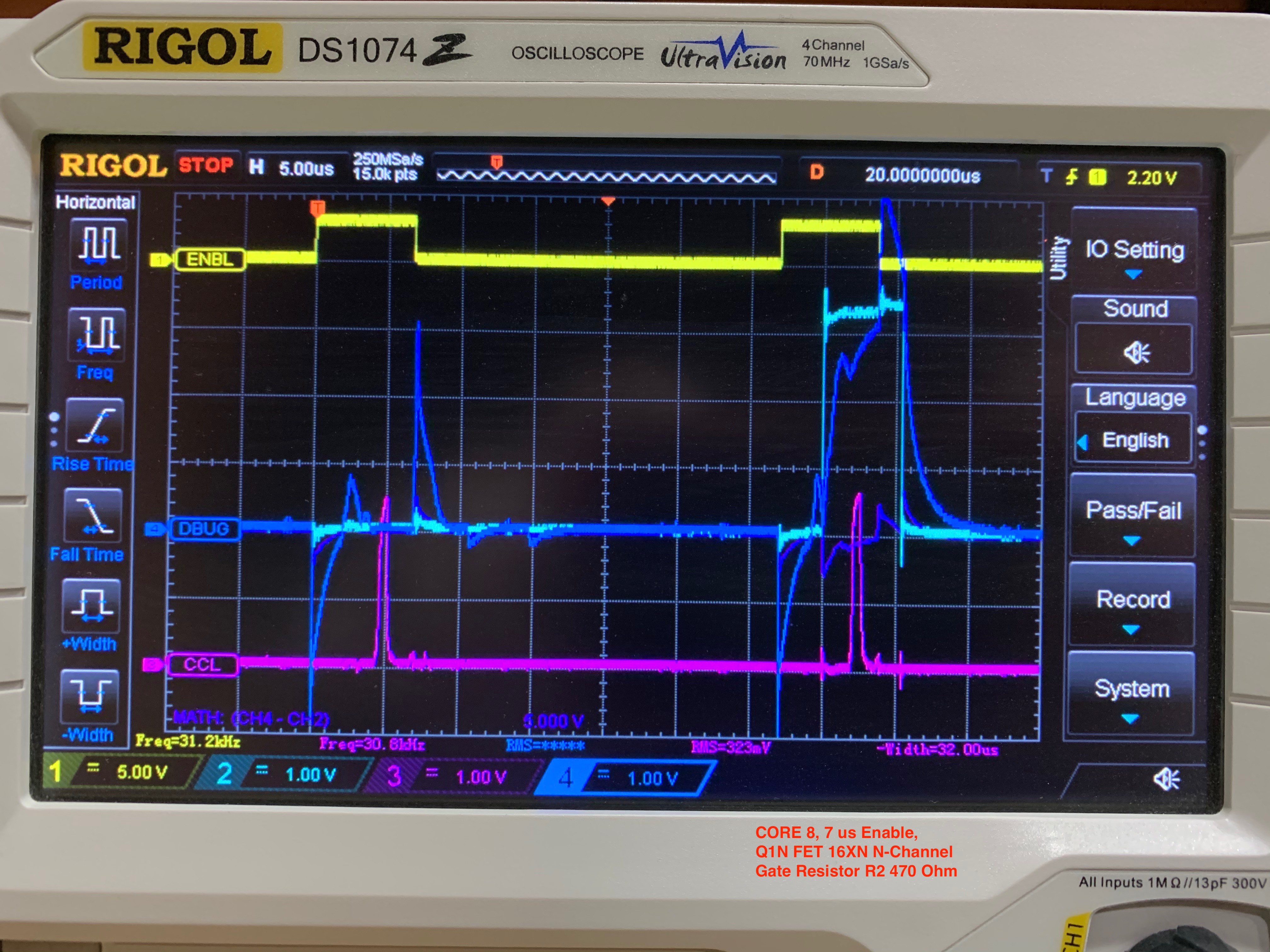
Cyan trace is the MCU side of the gate resistor, and the blue trace is the gate side of the resistor. That was a bad idea. So I started swapping FETs back to the original transistors, and things started working more and more. The most problematic FETs were the ones used in conjunction with the diode bridges (again, that's to minimize parts count). In some cores, I was seeing TWO sense pulses when there should have been one. Bottom line: design correctly to use FETs if you are going to use FETs. They require more care than transistors to implement. Things got much better with transistors:

You might notice another difference between the last two scope captures. The yellow line is the enable signal, and moving that turn-on and turn-off away from the matrix transistor changes helped square things up. I know the cyan and blue traces aren't as square as I'd like, and there is more to learn... but it works consistently now. And the overshoot isn't much to worry about, I reckon.
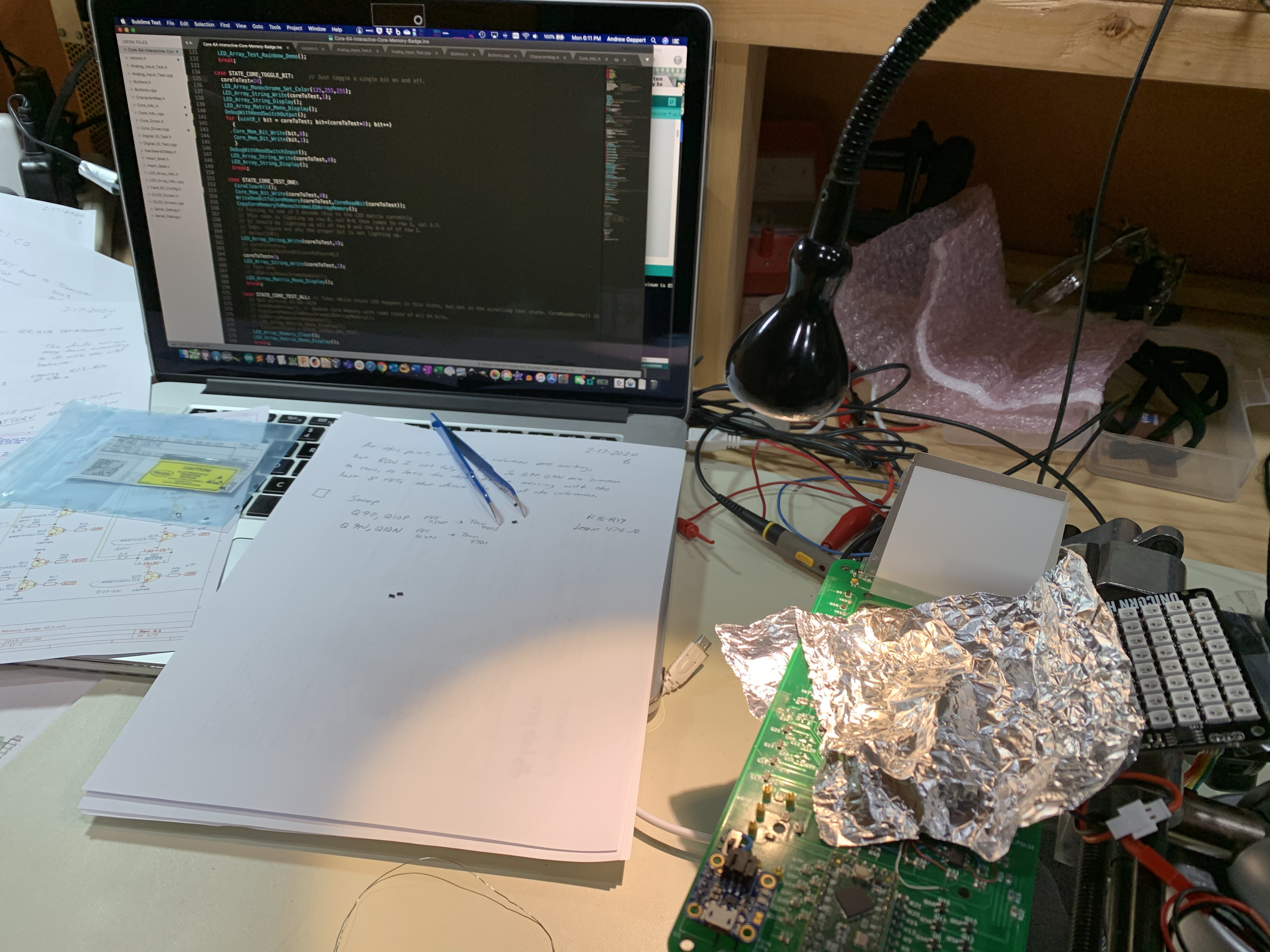
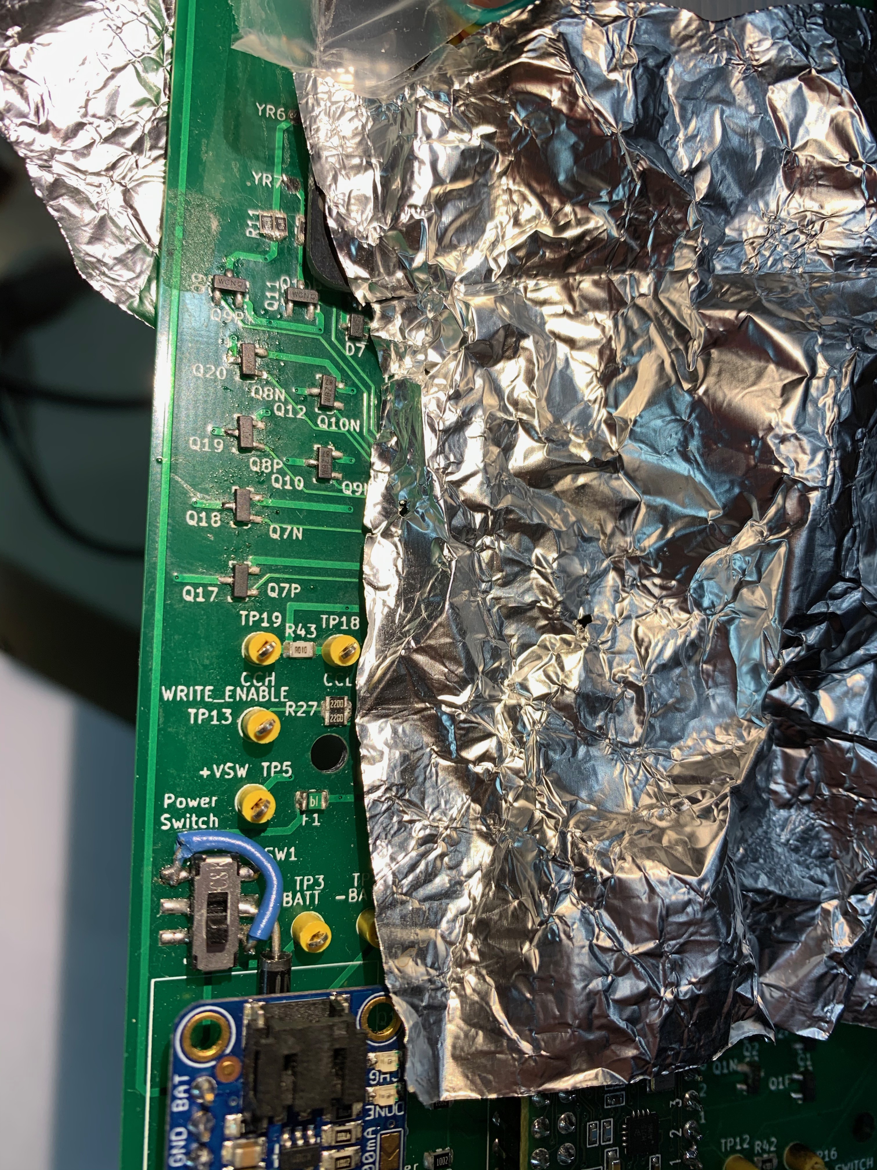
I spy a blue wire...
OK. Back on track now. The next step is to see if I can read the sense pulses and draw on the core memory screen! I am excited to see this come fully alive!
Discussions
Become a Hackaday.io Member
Create an account to leave a comment. Already have an account? Log In.