 jed
jedI need to go back and describe the circuit tailored to ride on the line-following robot. After I proved the concept and selected the alkaline cells to power it, I needed something that could ride on the robot. It needed to connect to the IC socket for its power and to control the motors, and it had to be able to hold the display. I decided to use a strip board and to stack the OLED on top of the NodeMCU. The strip board would plug into the IC socket and the other parts would plug into it. The wiring is pretty simple, so I planned it on in a notebook then wired it all up. Note the OLEDs in my stash sometimes swap the positions of the V+ and Gnd connections. Watch for that.
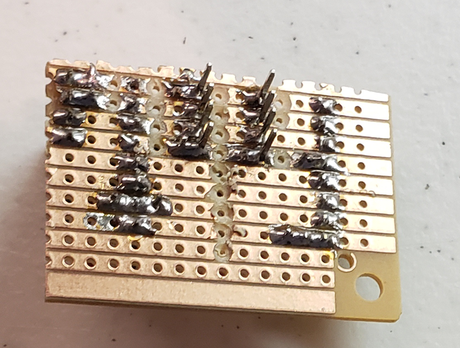
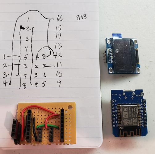 I used stripboard with male header pins to extend into the IC socket and five wires. Two red are V+, two black for Gnd and a green for a signal wire. The stripboard helped make the connections and saved me a few horizontal wires that are on the drawing. Note the socket on the left, for the OLED, has a second socket plugged into the first. This stacks the OLED above the NoteMCU.
 Once I had it properly installed into the robot's single IC socket, we have this familiar picture:
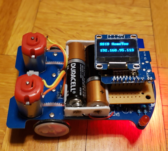
Discussions
Become a Hackaday.io Member
Create an account to leave a comment. Already have an account? Log In.