 Dan Julio
This log entry is ultimately about the circuit I use to interface to the analog telephone line but there is some fascinating history behind this part of the design.
Blue POT's deep roots
Voice telephony is about 170 years old at this writing. The first few decades were like the early days of micro-computers with lots of innovation and lots of different, incompatible, systems. This page has links to many articles detailing various historical aspects of telephony if you are interested in digging in further. Research I did shows that the origin of technology that Blue POT implements in 2019 first appeared over 130 years ago. Talk about backward compatibility...
- The names "Tip" and "Ring" that are still applied to the Green and Red wires in a twisted POTS line came about in the early 1880s as part of a plug used to connect calls in manual switchboards. The Ring (outside) is held at a negative potential to the Tip that is near ground potential. This was to prevent cathodic corrosion in long wire runs.
- Bell ringing voltages and cadences, originally generated by a customer cranked magneto, were put into service around the same time (80-100 VAC at 20 Hz). Over time this voltage became somewhat standardized although rural telephone exchanges often drove a higher signal (up to 150 VAC for party lines) to accommodate the long distances.
- The "Common Battery" system providing power at the central office first made an appearance in 1888 although the voltage levels that were finally standardized on by Bell in the USA, along with impedances, around the turn of the century. The -48V bias voltage we know today was based on 24-cell lead acid battery technology (nominally 52.1 volts at the central office).
- Although the first patent for a rotary dial was granted to Almon Brown Stowger in 1892, and there were some even earlier automated dialing systems, the rotary dial we know today made an appearance in the early 1900s. Fun fact: because it takes a lot longer to dial a 9 than a 1, Bell assigned the long-distance 3-digit area codes based on usage (the most frequently dialed areas got the quickest dialed area codes).
- The rotary dial reigned supreme for almost 60 years until the introduction of DTMF (dual tone multi-function) in 1963 although there were earlier telephones using keypads that converted button presses to pulse sequences simulating a rotary dial.
So you want to simulate a telephone line
I knew a few basic technical details about analog telephony when I started and figured I'd just hack something together that would work "well-enough". As a kid I saw an experiment where two phones were connected with a 6 volt lantern battery in series to provide enough power to talk. I also knew people successfully rang telephone bells with all kinds of voltage levels.
Initially I looked at circuits like this one and others that used discrete circuitry to interface the analog voice signals and impress ring voltages onto the line. However since I was going to hand-build the unit (at the time I thought I'd only make one) I was put off by all the wiring.
For my business I have kept my old landline phone number ported to Ooma's VOIP service and at some point realized that I had a telephone interface literally sitting on my desk. A few turns of a screw driver later and the Ooma - essentially a router that thinks it's a phone - lay apart in front of me.
This lead me into a world of new terms such as FXO, FXS and SLIC and the contemporary technology that implements them. I was going to design a FXS (Foreign Exchange Station - or Central Office) using a SLIC (Subscriber Line Interface Circuit).
More research ensued, starting with thinking about an ancient design from Motorola that was pretty straight forward but using more-or-less obsolete silicon to modern solutions from companies like Silicon Labs and Renesas aimed at VOIP solutions like the Ooma. These chips include codecs with serial interfaces and require external switch-mode DC-DC supplies to generate the telephone line bias and ring voltages. There are people who have successfully used them but they bring their own complexities to the table and some, like the Silicon Labs chips, seem to have documentation that exists only behind a corporate firewall. Although by this time I was convinced I wanted to build a proper telephone interface, at least for use on-premise, I was less enthused about the design because of the work now needed.
Along the way I had also seen some modules that appeared to have been used on line cards in central offices or PBX systems such as the Mitel HM88615. They incorporated circuitry to handle switching voltages and matching impedances to the telephone line. Initially I discounted them until I happened across the Silvertel AG1171. It was exactly what I wanted and at $6.07USD almost too good to be true - but it *is* the module you need if you want to play with old telephones, even if you only want to ring the bell, use the dial to control something else or deal with audio from the handset.
The AG1171S
The AG1171S is a 14-pin SIP and provides a complete interface, sans protective circuitry, to a phone line. It runs off 3.3-5V at less than 500 mA ringing a phone. It provides analog audio input and output signals, generates a -48V bias voltage and a -72V ring voltage, and detects the switch hook position (and rotary dial pulsing). It has 4 logic-level control signals (one is a power-down signal that I am not currently using). Super simple to use.
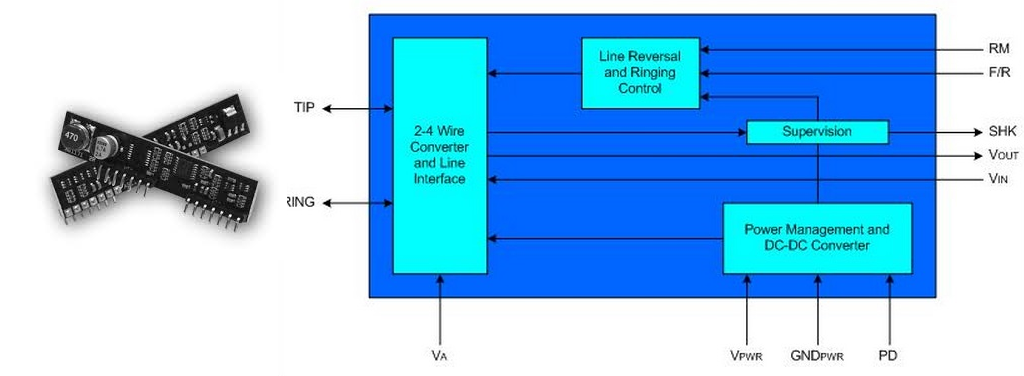
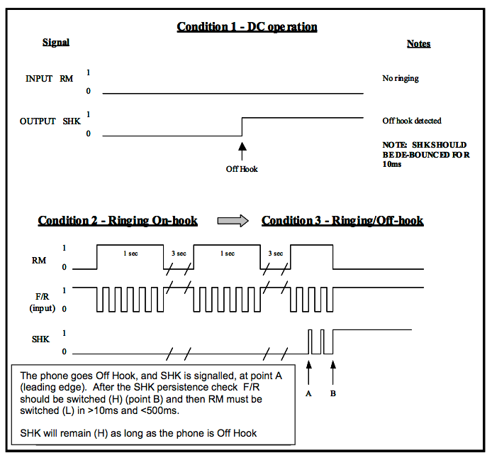
Two signals control its telephony function. The RM signal selects what voltage it drives onto the phone line. Normally it drives -48 volts to bias the line. RM is asserted during ringing to increase the voltage to -72 volts. Then the F/R signal is toggled at the ring rate (typically 20-25 Hz in the USA) to cause the bell to ring. The SHK signal is asserted when the switch hook is detected off-hook and toggles during rotary dialing. All illustrated in a figure from the specification below. Incredibly simple.
The AG1171 is designed for short loop "on premise" applications as opposed for use by a telephone company in their central office driving thousands of feet of line - in other words for devices like Blue POT. It does require some external protection circuitry. I implemented the circuitry recommended for ESD and EMI protection. The diodes shunt high voltages to ground or to an 82V rail provided by the zener. The capacitors reduce EMI. Apparently Silvertel has some documentation available for use with longer lines but I haven't looked at it.
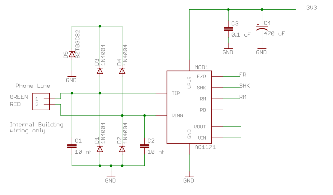
All that's needed for interfacing with your old telephones.
Decoding rotary dialing through switch-hook pulsing and the analog interface will be discussed in other logs.
Discussions
Become a Hackaday.io Member
Create an account to leave a comment. Already have an account? Log In.