 kodera2t
First of all, I made an adaptor with two BNCs and terminal adaptor for ADALM2000. The interface of ADALM2000 is just pin header and before I made this adaptor, every time I had to puzzle its connection.
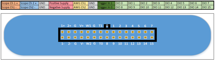
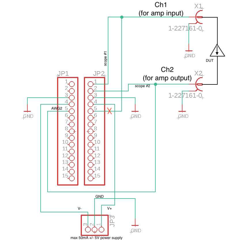
The schematic is as shown above. Ch 1 and 2 of the scope are connected to DUT (device under test). Indeed it is "counter intuitive" because one of two AWG (arbitral wave generator), AWG2 is connected to the output side of DUT. Initially I connected AWG1 and 2 for input and output, but AWG1 should be disconnected. The schematic above looks wrong, but it is the circuit measuring DUT in the direction of the image.
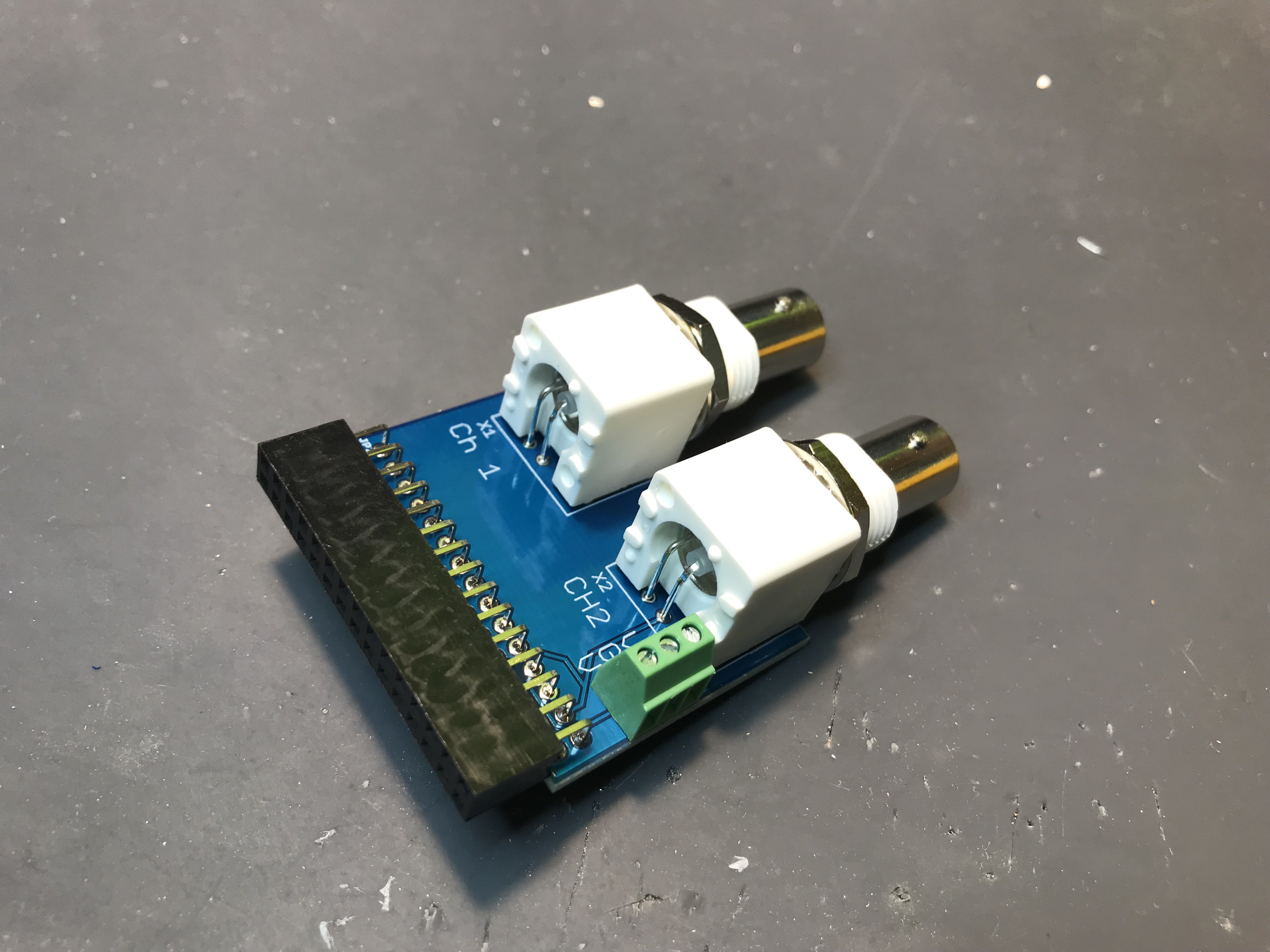
This is the completed adaptor for frequency response measurement. If we prepare AWG connection switch, it will be able to measure full two ports. Currently this is just for Ch1 to Ch2. Green terminal block is the power supply output inside ADALM2000. The power supply can generate max 50 mA, +/- 5V, which is suitable for quick operational amplifier circuit check.
Discussions
Become a Hackaday.io Member
Create an account to leave a comment. Already have an account? Log In.