 aloismbutura
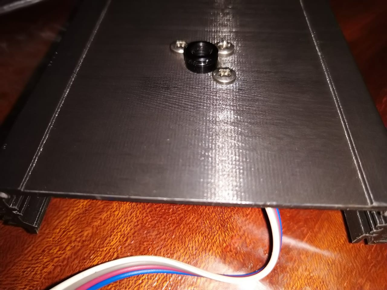
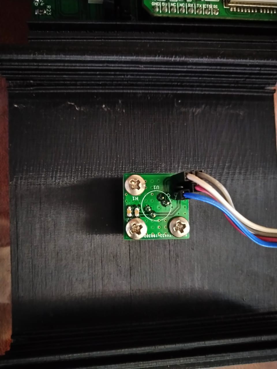
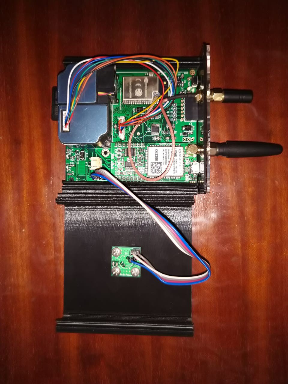
Assembling the Thermal array sensor add on board
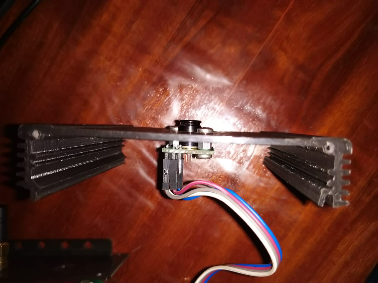
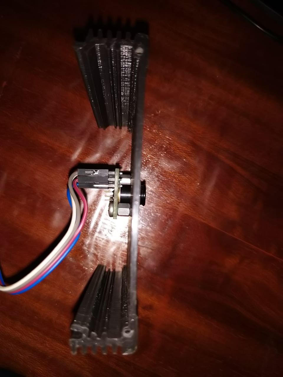
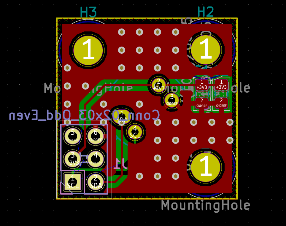
Errata 1: Footprint pinswap - Within the MLX90640 datasheet, the following pins are shown from bottom view. I ported the pins to footprint(Top view) without swapping the view of the pins within the datasheet. The end effect of this is that for the board to work, the top layer had to become the bottom when mounting- Luckily this change still worked well within the entire mechanical assembly without conflicts. Though this would mean the IDC connector would not work as expected as noted in Errata 2.
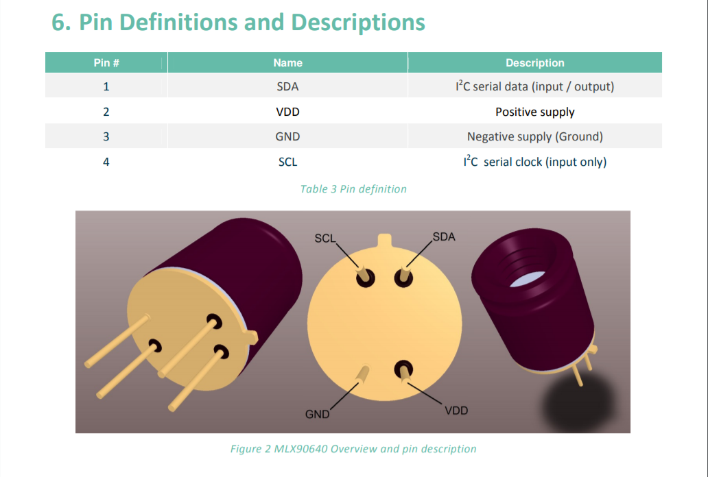
MLX90640 datasheet pin out
Top layer(Meant to face the Item in view of the MLX90640)Corrected board.
Corrected board.
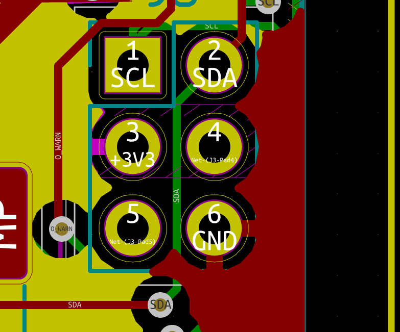
Errata 2: Due to the above errata 1, the 6 pin connector was swapped left-right/right-left due. The problem was remedied by using Female-Female jumpers instead of the desired 6 pin IDC cable. The design flaw can be seen below.
Footprint on add on board(bottom layer in layout).
Footprint on the top layer on the main board
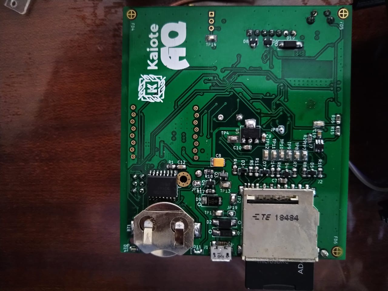
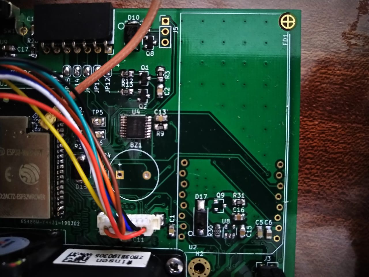
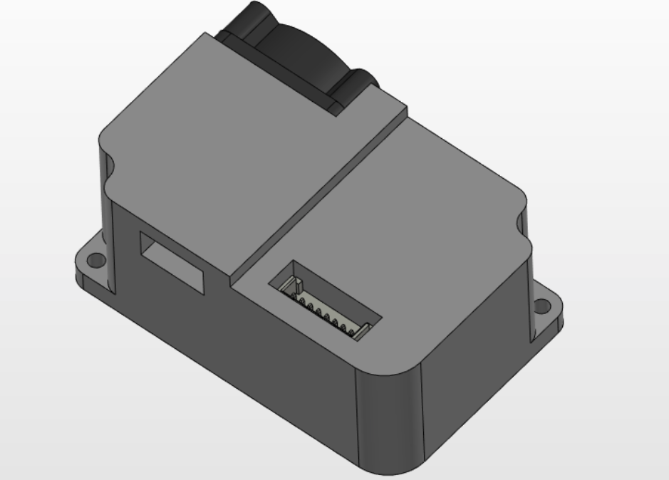
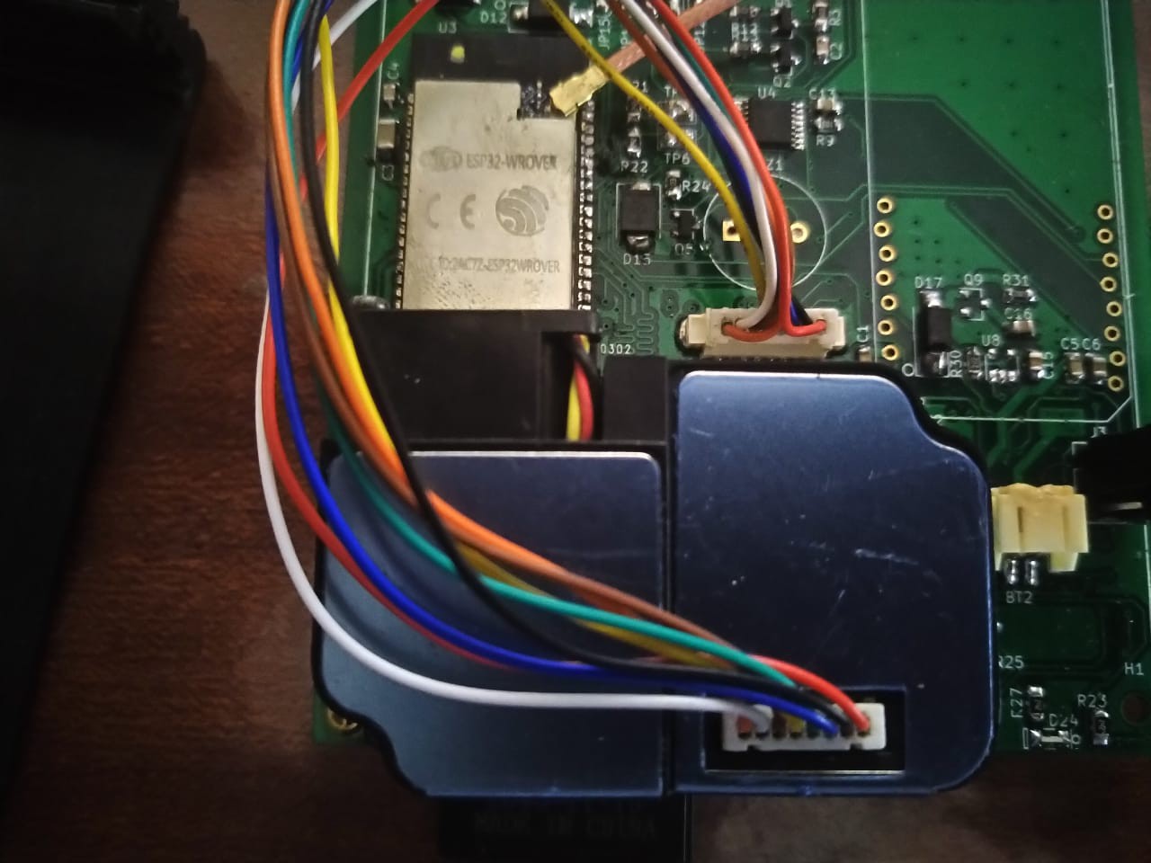
Assembling the main board
Cellular module
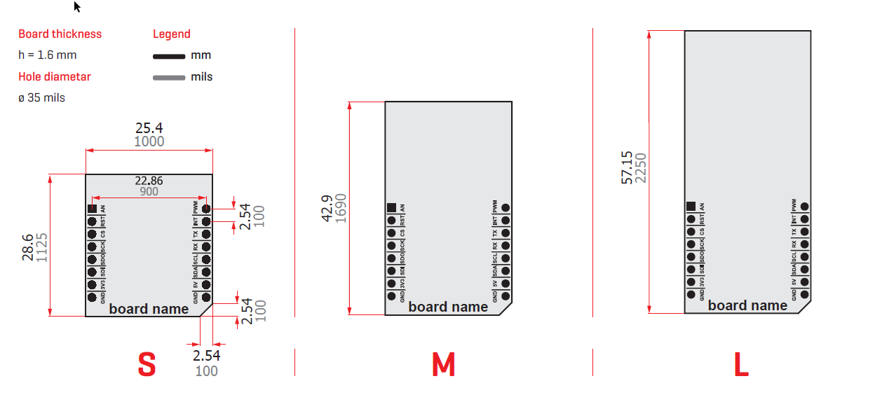
In order to have the ability to swap in and swap out various communication modules based on the Mikrobus footprint standard, the pins were staggered to allow a solderless connection. Each pin was moved off center alternating at 8 mils distance.
The above was ideal because the module chosen followed the Mikrobus open standard, it could easily be swapped out with another. Mikoelektronika has a whole list of Mikrobus modules. This allows one to choose between the following modules:
Note: as at a version 1 on the hardware level, only cellular is possible as I only implemented the UART(TX/RX) and power portion of the Mikrobus standard.

Particulate matter sensor
For the particulate matter sensor I used the ZH03B from Winsen electronics. Though the calibration for these sensors are not traceable, the thought is that low cost sensors can be used to show a decrease in pollutant exposure over time as opposed to being used for absolute point measurements.
The ZH03B part did not have a 3D model, I thus created the 3D model in onshape for all variants of the part which include the ZH03, ZH03A and ZH03B. The 3D STEP models can be downloaded from grabcad.
The connector to be placed on the PCB that integrates this sensor is the Boom Precision Elec 1.25T-8P with part number C53040. The Molex picoblade series part number 0533980871can also be substituted for the Boom precision part. Do note the connector is shrouded,thus polarised, therefore you cannot rotate it 180 degrees in case the electrical connections are swapped during design unless by physical removal of one of the shroud walls after PCB placement.
Errata 3: wrong particulate matter sensor placement-rotated 180 degrees-As can be seen below the footprint pinout was swapped in footprint design. Meaning that Pin 8 on the sensor would be connected to Pin 1 on the main board connector and so on. The remedy was to remove the shroud on the connector, meaning I could invert the cable 180 degrees.
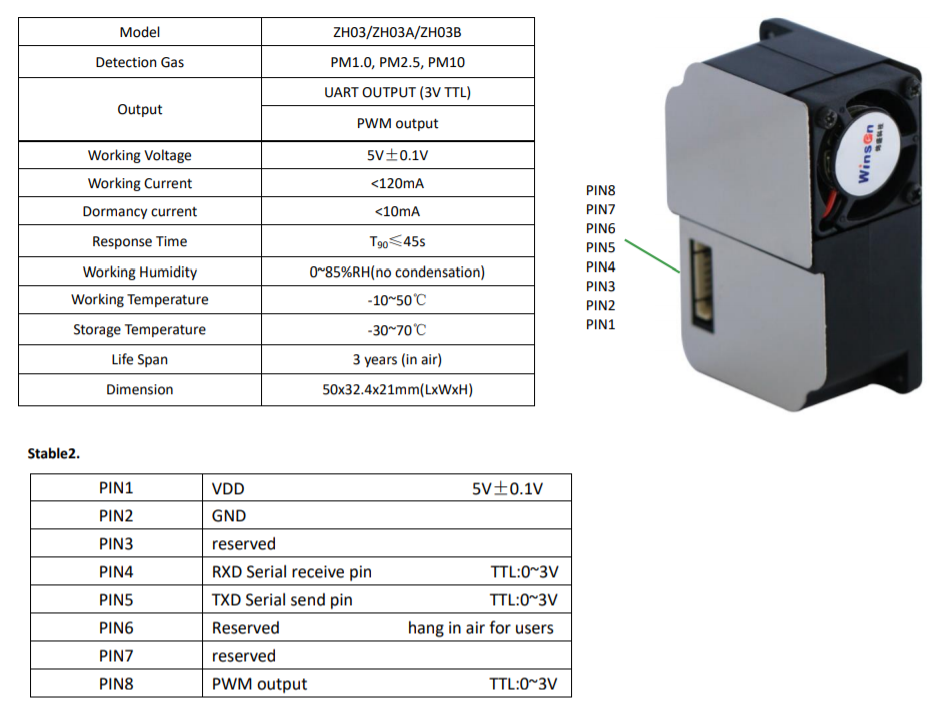 ZH03B pinout
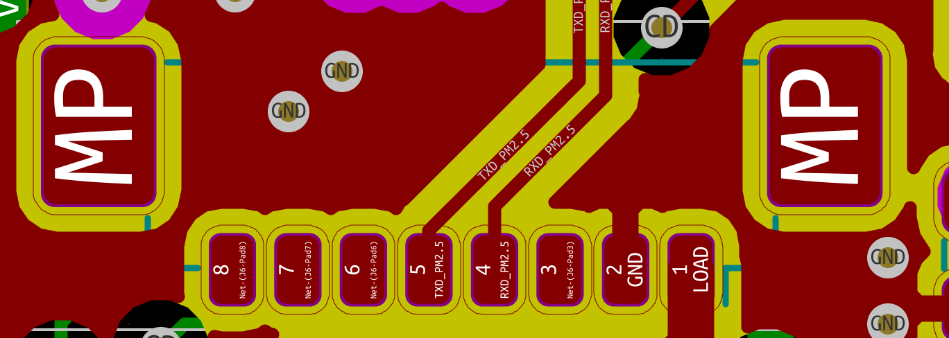
Main board top layer view
Buzzer
Errata 4: Wrong buzzer selection: The wrong buzzer was selected. Within my schematic, I designed for a self excited buzzer(Constant frequency - usually 2 kHz) but when doing the ordering I chose an externally excited buzzer that required an external oscillator circuit to drive it!(Varying audible frequency as a result)
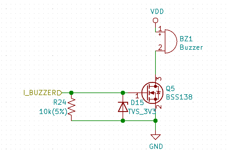
Internally excited buzzer control schematic
Discussions
Become a Hackaday.io Member
Create an account to leave a comment. Already have an account? Log In.